Papermaking system
阅读说明:本技术 一种造纸系统 (Papermaking system ) 是由 黄水源 于 2021-07-06 设计创作,主要内容包括:本发明公开了一种造纸系统,包括基座,所述基座顶面固定设有两个左右对称的支撑块,两个所述支撑块之间固定设有卸料壳,所述卸料壳内开设有卸料腔,所述卸料壳顶面上固定设有外壳,所述基座右侧固定设有基台,所述基台顶面内开设有装料腔,所述基台顶面上垂直固定设有支撑板,所述支撑板右侧面上固定设有进风管,所述外壳左侧面上固定设有进水管,所述支撑板内滑动设有滑动板,所述支撑板左侧面开设有滑动口,所述滑动口内滑动设有向左延伸的晾干板,本发明使回收废纸重新转变为可使用的纸质产品,节省了造纸工艺所需要的人工成本,且本发明相对于原浆造纸系统,不仅减少了造纸工艺对环境的破坏,也减少了造纸工厂所产生的污染废水。(The invention discloses a papermaking system, which comprises a base, wherein two bilaterally symmetrical supporting blocks are fixedly arranged on the top surface of the base, a discharging shell is fixedly arranged between the two supporting blocks, a discharging cavity is formed in the discharging shell, a shell is fixedly arranged on the top surface of the discharging shell, a base station is fixedly arranged on the right side of the base, a charging cavity is formed in the top surface of the base station, a supporting plate is vertically and fixedly arranged on the top surface of the base station, an air inlet pipe is fixedly arranged on the right side surface of the supporting plate, a water inlet pipe is fixedly arranged on the left side surface of the shell, a sliding plate is arranged in the supporting plate in a sliding manner, a sliding opening is formed in the left side surface of the supporting plate, and a drying plate extending leftwards is arranged in the sliding opening in a sliding manner, not only reduces the damage of the papermaking process to the environment, but also reduces the pollution waste water generated by the papermaking factory.)
1. The utility model provides a papermaking system, includes the base, the fixed supporting shoe that is equipped with two bilateral symmetry of base top surface, its characterized in that: a discharging shell is fixedly arranged between the two supporting blocks, the left side surface and the right side surface of the discharging shell are respectively fixed with the supporting blocks at the same side, a discharging cavity is formed in the discharging shell, a shell is fixedly arranged on the top surface of the discharging shell, a stirring cavity is formed in the shell, a discharging pipe is fixedly arranged on the top surface of the base, the discharging pipe vertically penetrates through the bottom surface of the discharging shell, a fixed block is fixedly arranged on the top surface of the discharging pipe, a stirring rod is rotatably arranged on the top surface of the fixed block, two stirring plates which are bilaterally symmetrical are fixedly arranged on the periphery of the stirring rod, two support columns which are bilaterally symmetrical are fixedly arranged on the top surface of the shell, a feeding shell is fixedly arranged between the two support columns, the left side surface and the right side surface of the feeding shell are respectively fixed with the support columns at the same side, a paper shredding shell is fixedly arranged on the bottom surface of the feeding shell, and a conveying pipe is fixedly arranged on the right side surface of the discharging pipe, run through the right side about the transport pipe the supporting shoe, the fixed base station that is equipped with in base right side, the chamber of charging has been seted up in the base station top surface, run through about the transport pipe right-hand member the chamber left wall of charging, the vertical fixation is equipped with the backup pad on the base station top surface, the fixed air-supply line that is equipped with on the backup pad right flank, the fixed inlet tube that is equipped with on the shell left surface, it is equipped with the sliding plate to slide in the backup pad, the sliding opening has been seted up to the backup pad left surface, the slip is equipped with the board that dries that extends left in the sliding opening, dry the board right-hand member with the sliding plate left surface is fixed.
2. A papermaking system according to claim 1, characterised in that: a paper shredding cavity is arranged in the paper shredding shell, two paper shredding shafts which are arranged at the front and the rear opposite sides are fixedly arranged on the inner wall of the paper shredding cavity, two paper shredding power sources which are symmetrical in the front and the back are fixedly arranged in the paper shredding shell, the two paper shredding power sources are respectively in power connection with the paper shredding shafts on the same side, first paper shredding wheels which are arranged at equal intervals are fixedly arranged on the periphery of the paper shredding shaft on the front side, second paper shredding wheels which are arranged at equal intervals are fixedly arranged on the periphery of the paper shredding shaft on the back side, each second paper shredding wheel is respectively positioned between the two first paper shredding wheels which are separated from each other nearest, the top surface of the shell is provided with a feed inlet, the bottom surface of the paper shredding shell is provided with an opening which is communicated with the feed inlet, the paper shredding power source is started, the waste paper is put into the feed shell, the waste paper is shredded through the first paper shredding wheel and the second paper shredding wheel, and finally shredded waste paper enters the stirring cavity through the feed inlet from the paper shredding cavity.
3. A papermaking system according to claim 2, characterised in that: the stirring intracavity slides and is equipped with the filter screen, the filter screen outer peripheral face with the laminating of stirring intracavity wall, the equal fixed restriction pole that is equipped with of filter screen left and right ends, set up two bilateral symmetry's restriction groove on the stirring intracavity wall, two the restriction pole inserts the homonymy respectively the restriction inslot, the puddler runs through from top to bottom the filter screen, two the restriction inslot all rotates and is equipped with the restriction gear shaft, two all fixed restriction gear, two in the restriction gear shaft periphery all be equipped with the restriction gear, two restriction gear respectively with the homonymy the restriction pole meshing, two all fixed restriction power supply, two in the restriction inslot the restriction power supply respectively with the homonymy restriction gear shaft power is connected, opens the restriction power supply makes restriction gear revolve makes the restriction pole with the filter screen reciprocates.
4. A papermaking system according to claim 3, characterised in that: the rotary power source is fixedly arranged in the fixed block and is in power connection with the stirring rod, a millstone is fixedly arranged on the periphery of the stirring rod, a drain pan is fixedly arranged on the inner wall of the stirring cavity, the stirring rod penetrates through the drain pan from top to bottom, a leak is arranged between the inner circumferential surface of the drain pan and the outer circumferential surface of the stirring rod, the bottom surface of the millstone is attached to the top surface of the drain pan, but liquid can pass through the space between the millstone and the drain pan, the stirring cavity is communicated with the discharging cavity, the millstone is positioned at the lower side of the stirring plate, the filter screen is positioned between the millstone and the stirring plate, a discharging transportation cavity is arranged in the discharging pipe, a discharging opening is arranged on the rear wall of the transportation cavity, a discharging channel is arranged in the bottom wall of the transportation cavity, two heating cavities which are bilaterally symmetrical are arranged in the stirring rod, and heating wires which are equidistantly arranged from top to bottom are fixed in the two heating cavities, the puddler internal fixation is equipped with two bilateral symmetry's heating power supply, two heating power supply respectively with the homonymy the heater strip power is connected, opens the rotation power supply makes the puddler rotates, makes the stirring board with the mill rotates, opens simultaneously heating power supply makes the heater strip generates heat, makes it heaies up in the stirring chamber.
5. A papermaking system according to claim 4, characterised in that: the passageway right port of unloading with the transport pipe communicates with each other, it is equipped with five frames that dry to turn right the slip from a left side in the cavity of feeding, five it can follow to dry the frame homoenergetic the intracavity roll-off that makes progress of feeding, every dry the frame left and right sides on all fixed two chains that are equipped with symmetry around, every the chain top all with it is fixed to dry the board bottom surface the backup pad internal rotation is equipped with the slip gear shaft, the fixed slip gear that is equipped with in the slip gear shaft periphery, the slip gear with sliding plate right flank meshing, the backup pad internal fixation is equipped with the slip power supply, the slip power supply with slip gear shaft power is connected, opens the slip power supply, makes the slip gear rotates, makes the sliding plate with it reciprocates to dry the board, makes it reciprocates to dry the frame.
6. A papermaking system according to claim 5, characterised in that: the drying plate is internally provided with a ventilation cavity, five ventilation openings are formed in the bottom wall of the ventilation cavity from left to right, five ventilation openings are respectively aligned with five drying frames from left to right in sequence, five pressing plates are arranged in the ventilation cavity from left to right in a sliding manner, five push rods are arranged in the drying plate from left to right in a sliding manner, five bottom ends of the push rods are respectively fixed on the top surfaces of the five pressing plates from left to right in sequence, the five pressing plates are respectively aligned with the five ventilation openings from left to right in sequence, the drying plate is internally provided with five push rod gear shafts from left to right in a rotating manner, the periphery of the five push rod gear shafts is fixedly provided with push rod gears, the five push rod gears are respectively meshed with the push rods at the same side, the drying plate is internally provided with five push rod power sources from left to right in a fixed manner, and the five push rod power sources are respectively in power connection with the push rod gear shafts at the same side, the utility model discloses a ventilation air conditioner, including backup pad, air transmission channel, push rod gear, air inlet pipe, air transmission channel left port, air transmission channel right-hand member mouth, air inlet pipe, air outlet pipe, air transmission channel right port with the air-supply line communicates with each other, air transmission channel left port can with the right-hand member mouth in the chamber that ventilates communicates with each other, opens the push rod power supply, makes the push rod with the clamp plate downstream makes the clamp plate is followed air-dry inboard roll-off, until the clamp plate slips in air-dry in the frame, and work as air-dry board rebound, until the chamber that ventilates with when air transmission channel communicates with each other, let in the air-supply pipe in steam, make air transmission channel with the chamber that ventilates follows the vent blows out.
Technical Field
The invention relates to the technical field of papermaking, in particular to a papermaking system.
Background
The paper production is divided into two basic processes of paper pulp and paper making, the paper pulp making in the primary pulp paper making is to dissociate the plant fiber raw material into the natural color paper pulp or bleached paper pulp, but not only a large amount of plants are consumed as raw materials, but also a large amount of sewage which is difficult to treat is generated in the paper making process, and great damage is caused to the natural environment.
Disclosure of Invention
The object of the present invention is to provide a papermaking system for overcoming the above-mentioned drawbacks of the prior art.
The papermaking system comprises a base, wherein two bilaterally symmetrical supporting blocks are fixedly arranged on the top surface of the base, a discharging shell is fixedly arranged between the two supporting blocks, the left side surface and the right side surface of the discharging shell are respectively fixed with the supporting blocks on the same side, a discharging cavity is formed in the discharging shell, a shell is fixedly arranged on the top surface of the discharging shell, a stirring cavity is formed in the shell, a discharging pipe is fixedly arranged on the top surface of the base, the discharging pipe vertically penetrates through the bottom surface of the discharging shell, a fixed block is fixedly arranged on the top surface of the discharging pipe, a stirring rod is rotatably arranged on the top surface of the fixed block, two bilaterally symmetrical stirring plates are fixedly arranged on the periphery of the stirring rod, two bilaterally symmetrical supporting columns are fixedly arranged on the top surface of the shell, a feeding shell is fixedly arranged between the two supporting columns, and the left side surface and the right side surface of the feeding shell are respectively fixed with the supporting columns on the same side, the utility model discloses a quick-witted loading and unloading system, including feeding shell, unloading pipe, supporting shoe, charging chamber, slide plate and air-drying plate, the fixed shredded paper shell that is equipped with on the feeding shell bottom surface, the fixed transport pipe that is equipped with on the unloading pipe right flank, run through the right side about the transport pipe the supporting shoe, the fixed base station that is equipped with in base right side, the chamber of charging has been seted up in the base station top surface, run through about the transport pipe right-hand member the chamber left wall of charging, the vertical fixation is equipped with the backup pad on the base station top surface, the fixed air-supply line that is equipped with on the backup pad right flank, the fixed inlet tube that is equipped with on the shell left surface, slide plate in the backup pad, the slide plate left surface has been seted up the slip mouth, slide plate internal slip is equipped with the board that dries the left side extends, dry the board right-hand member with the slide plate left surface is fixed.
In a further technical scheme, a paper shredding cavity is formed in the paper shredding shell, two paper shredding shafts which are arranged at the front and back opposite sides are fixedly arranged on the inner wall of the paper shredding cavity, two paper shredding power sources which are symmetrical in the front and the back are fixedly arranged in the paper shredding shell, the two paper shredding power sources are respectively in power connection with the paper shredding shafts on the same side, first paper shredding wheels which are arranged at equal intervals are fixedly arranged on the periphery of the paper shredding shaft on the front side, second paper shredding wheels which are arranged at equal intervals are fixedly arranged on the periphery of the paper shredding shaft on the back side, each second paper shredding wheel is respectively positioned between the two first paper shredding wheels which are separated from each other nearest, the top surface of the shell is provided with a feed inlet, the bottom surface of the paper shredding shell is provided with an opening which is communicated with the feed inlet, the paper shredding power source is started, the waste paper is put into the feed shell, the waste paper is shredded through the first paper shredding wheel and the second paper shredding wheel, and finally shredded waste paper enters the stirring cavity through the feed inlet from the paper shredding cavity.
In a further technical scheme, a filter screen is arranged in the stirring cavity in a sliding manner, the peripheral surface of the filter screen is attached to the inner wall of the stirring cavity, the left end and the right end of the filter screen are both fixedly provided with a limiting rod, the inner wall of the stirring cavity is provided with two bilaterally symmetrical limiting grooves, the two limiting rods are respectively inserted into the limiting grooves at the same side, the puddler runs through from top to bottom the filter screen, two the restriction inslot all rotates and is equipped with the restriction gear shaft, two all fixedly on the restriction gear shaft periphery is equipped with the restriction gear, two restriction gear respectively with the homonymy the restriction bar meshing, two all fixedly in the restriction inslot is equipped with the restriction power supply, two the restriction power supply respectively with the homonymy restriction gear shaft power is connected, opens the restriction power supply makes restriction gear rotates, makes the restriction pole with the filter screen reciprocates.
The technical scheme is that a rotary power source is fixedly arranged in a fixed block and is in power connection with a stirring rod, a millstone is fixedly arranged on the periphery of the stirring rod, a drain pan is fixedly arranged on the inner wall of a stirring cavity, the stirring rod penetrates through the drain pan from top to bottom, a leak is arranged between the inner circumferential surface of the drain pan and the outer circumferential surface of the stirring rod, the bottom surface of the millstone is attached to the top surface of the drain pan, but liquid can pass through the space between the millstone and the drain pan, the stirring cavity is communicated with a discharging cavity, the millstone is positioned at the lower side of a stirring plate, a filter screen is positioned between the millstone and the stirring plate, a discharging transportation cavity is arranged in a discharging pipe, a discharging opening is arranged on the rear wall of the transportation cavity, a discharging channel is arranged in the bottom wall of the transportation cavity, and two bilaterally symmetrical heating cavities are arranged in the stirring rod, two it is equipped with from the heater strip down equidistance range to heat the intracavity all to fix, the puddler internal fixation is equipped with the heating power supply of two bilateral symmetry, two the heating power supply respectively with the homonymy the heater strip power is connected, opens rotate the power supply, makes the puddler rotates, makes the stirring board with the mill rotates, opens simultaneously the heating power supply makes the heater strip generates heat, makes the stirring intracavity intensifies.
Further technical scheme, the passageway right port of unloading with the conveying pipe communicates with each other, it is equipped with five frames that dry to turn right the slip from a left side in the charging chamber, five it can follow to dry the frame homoenergetic the charging chamber roll-off that makes progress, every it all fixes the chain that is equipped with two longitudinal symmetries on the frame left and right sides, every the chain top all with it is fixed to dry the board bottom surface the backup pad internal rotation is equipped with the slip gear shaft, the fixed slip gear that is equipped with in slip gear shaft periphery, the slip gear with sliding plate right flank meshing, the backup pad internal fixation is equipped with the slip power supply, the slip power supply with slip gear shaft power is connected, opens the slip power supply, makes the slip gear rotates, makes the sliding plate with dry the board and reciprocate, then dry the frame and reciprocate.
A ventilation cavity is formed in the drying plate, five ventilation openings are formed in the bottom wall of the ventilation cavity from left to right, five ventilation openings are respectively aligned with five drying frames from left to right in sequence from top to bottom, five pressing plates are arranged in the ventilation cavity from left to right in a sliding manner, five push rods are arranged in the drying plate from left to right in a sliding manner, five bottom ends of the push rods are respectively fixed on the top surfaces of the five pressing plates from left to right in a corresponding manner, five pressing plates are respectively aligned with five ventilation openings from left to right in a corresponding manner, five push rod gear shafts are rotatably arranged in the drying plate from left to right, push rod gears are fixedly arranged on the periphery of the five push rod gear shafts, the five push rod gears are respectively meshed with the push rods on the same side, five push rod power sources are fixedly arranged in the drying plate from left to right, and are respectively in power connection with the push rod gear shafts on the same side, the utility model discloses a ventilation air conditioner, including backup pad, air transmission channel, push rod gear, air inlet pipe, air transmission channel left port, air transmission channel right-hand member mouth, air inlet pipe, air outlet pipe, air transmission channel right port with the air-supply line communicates with each other, air transmission channel left port can with the right-hand member mouth in the chamber that ventilates communicates with each other, opens the push rod power supply, makes the push rod with the clamp plate downstream makes the clamp plate is followed air-dry inboard roll-off, until the clamp plate slips in air-dry in the frame, and work as air-dry board rebound, until the chamber that ventilates with when air transmission channel communicates with each other, let in the air-supply pipe in steam, make air transmission channel with the chamber that ventilates follows the vent blows out.
The invention relates to a papermaking system, which comprises the following working procedures:
the paper shredding function is as follows:
open the shredded paper power supply, put into waste paper in the feeding shell, through first shredded paper wheel with the second shredded paper wheel makes waste paper is shredded, and final shredded waste paper is followed the shredded paper intracavity passes through the feed inlet gets into the stirring intracavity.
Pulping function:
through the inlet tube, make the processing solution flow into the stirring intracavity, until the processing solution top surface floods the puddler top, open simultaneously heating power, make the heater strip generates heat, makes the processing solution intensifies.
Turning on the rotary power source to enable the stirring rod to rotate, enabling the stirring plate and the grinding disc to rotate, enabling the surface of the waste paper to be in full contact with the treatment liquid through the stirring plate, enabling the waste paper to be primarily stirred and crushed in the treatment liquid through the stirring plate to form a mixed liquid, simultaneously turning on the limiting power source to enable the limiting gear to rotate, enabling the limiting rod and the filter screen to move up and down, enabling the mixed liquid to remove impurities in the mixed liquid through the filter screen, enabling the mixed liquid to form a slurry through fine grinding of the grinding disc and the leakage disc, and enabling the slurry to flow into the discharging cavity through the leakage opening;
the slurry flows into the charging cavity through the discharge opening, the conveying cavity, the discharge pipeline and the conveying pipe in sequence until the charging cavity is filled with the slurry.
Go out the paper and dry the function:
starting a sliding power source to enable the sliding gear to rotate, enabling the sliding plate and the airing plate to move upwards, enabling the airing frame to move upwards until the ventilation cavity is communicated with the air transmission channel, enabling the airing frame to slide out of the charging cavity, and enabling papermaking materials in the slurry to be reserved in the airing frame;
starting a push rod power source, enabling a push rod gear to rotate, enabling the push rod and the pressing plate to move downwards, enabling the pressing plate to slide out of the drying plate downwards until the pressing plate slides into the drying frame, enabling the papermaking materials to be pressed and leveled in the drying frame, and rotating the push rod gear to enable the pressing plate to return to an initial position in the ventilation cavity;
hot air is introduced into the air inlet pipe, so that the hot air is blown out of the ventilation opening through the air conveying channel and the ventilation cavity, and the hot air is finally blown on the top surface of the papermaking material until moisture in the papermaking material is dried to form a paper product;
and finally taking out the paper product from the airing frame.
The invention has the beneficial effects that: the paper making system provided by the invention has the advantages that the recycled waste paper is converted into the usable paper products again through the processes of automatic shredding, automatic pulping and automatic airing, the labor cost required by the paper making process is saved, in addition, compared with a virgin pulp paper making system, the damage of the paper making process to the environment is reduced, and the pollution waste water generated by a paper making factory is also reduced.
Drawings
FIG. 1 is a schematic external view of a papermaking system of the present invention;
FIG. 2 is a schematic cross-sectional view of a papermaking system of the present invention;
FIG. 3 is a schematic drawing showing a left side partial cross-section of a papermaking system of the present invention;
FIG. 4 is a schematic drawing in section of the right side portion of a papermaking system of the present invention;
FIG. 5 is an enlarged view of a portion of FIG. 3 according to the present invention;
fig. 6 is a partially enlarged view of the invention at B in fig. 4.
Detailed Description
For purposes of making the objects and advantages of the present invention more apparent and the invention is more clearly described below in connection with the examples, it is to be understood that the following text is intended merely to describe a papermaking system or several specific embodiments of the invention and does not strictly limit the scope of the invention as specifically claimed, as used herein, the terms upper and lower and left and right are not limited to their strict geometric definitions, but include tolerances for reasonable and inconsistent machining or human error, the specific features of which are set forth in detail below:
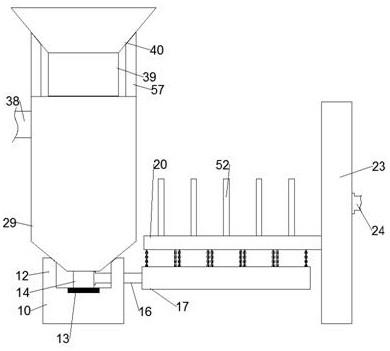
referring to fig. 1-6, a papermaking system according to an embodiment of the present invention includes a base 10, two bilaterally symmetrical support blocks 12 are fixed on a top surface of the base 10, a discharge casing 58 is fixed between the two support blocks 12, left and right sides of the discharge casing 58 are respectively fixed to the same support blocks 12, a discharge chamber 59 is formed in the discharge casing 58, a housing 29 is fixed on a top surface of the discharge casing 58, a stirring chamber 32 is formed in the housing 29, a discharge pipe 14 is fixed on the top surface of the base 10, the discharge pipe 14 vertically penetrates through a bottom surface of the discharge casing 58, a fixed block 60 is fixed on a top surface of the discharge pipe 14, a stirring rod 61 is rotatably formed on a top surface of the fixed block 60, two bilaterally symmetrical stirring plates 37 are fixed on an outer periphery of the stirring rod 61, two bilaterally symmetrical support pillars 57 are fixed on the top surface of the housing 10, a feeding shell 40 is fixedly arranged between the two supporting columns 57, the left side and the right side of the feeding shell 40 are respectively fixed with the supporting columns 57 at the same side, a paper scrap shell 39 is fixedly arranged on the bottom surface of the feeding shell 40, a conveying pipe 16 is fixedly arranged on the right side of the discharging pipe 14, the supporting block 12 at the right side penetrates through the left side and the right side of the conveying pipe 16, a base table 17 is fixedly arranged on the right side of the base 10, a charging cavity 54 is formed in the top surface of the base table 17, a left wall of the charging cavity 54 penetrates through the right side and the left side of the right end of the conveying pipe 16, a supporting plate 23 is vertically and fixedly arranged on the top surface of the base table 17, an air inlet pipe 24 is fixedly arranged on the right side of the supporting plate 23, a water inlet pipe 38 is fixedly arranged on the left side of the shell 29, a sliding plate 28 is arranged in the supporting plate 23, a sliding opening 48 is formed in the left side of the supporting plate 23, and a drying plate 20 extending leftwards is arranged in the sliding opening 48, the right end of the drying plate 20 is fixed to the left side of the sliding plate 28.
Beneficially or exemplarily, a shredding chamber 41 is formed in the shredding shell 39, two shredding shafts 42 which are opposite to each other in the front and back directions are fixedly arranged on the inner wall of the shredding chamber 41, two shredding power sources which are symmetrical in the front and back directions are fixedly arranged in the shredding shell 39, the two shredding power sources are respectively in power connection with the shredding shafts 42 on the same side, first shredding wheels 56 which are arranged at equal intervals are fixedly arranged on the periphery of the shredding shaft 42 on the front side, second shredding wheels 43 which are arranged at equal intervals are fixedly arranged on the periphery of the shredding shaft 42 on the back side, each second shredding wheel 43 is respectively positioned between the two first shredding wheels 56 which are closest to each other, a feeding port 62 is formed in the top surface of the outer shell 29, an opening in the bottom surface of the shredding shell 39 is communicated with the feeding port 62, the shredding power sources are turned on, waste paper is put into the feeding shell 40, and the first shredding wheels 56 and the second shredding wheels 43, the used paper is shredded, and the finally shredded used paper enters the stirring chamber 32 from the paper shredding chamber 41 through the feed port 62.
Beneficially or exemplarily, a filter screen 35 is slidably disposed in the stirring cavity 32, an outer peripheral surface of the filter screen 35 is attached to an inner wall of the stirring cavity 32, the left and right ends of the filter screen 35 are both fixedly provided with a limiting rod 36, the inner wall of the stirring cavity 32 is provided with two bilaterally symmetrical limiting grooves 46, the two limiting rods 36 are respectively inserted into the limiting grooves 46 on the same side, the stirring rod 61 vertically penetrates through the filter screen 35, the two limiting grooves 46 are both rotatably provided with a limiting gear shaft 44, the outer peripheries of the two limiting gear shafts 44 are both fixedly provided with limiting gears 45, the two limiting gears 45 are respectively engaged with the limiting rods 36 on the same side, the two limiting grooves 46 are both fixedly provided with limiting power sources, the two limiting power sources are respectively in power connection with the limiting gear shafts 44 on the same side, the limiting power sources are turned on to enable the limiting gears 45 to rotate, the restricting bar 36 and the screen 35 are moved up and down.
Beneficially or exemplarily, a rotary power source 13 is fixedly arranged in the fixed block 60, the rotary power source 13 is in power connection with the stirring rod 61, a grinding disc 34 is fixedly arranged on the outer periphery of the stirring rod 61, a leakage disc 33 is fixedly arranged on the inner wall of the stirring cavity 32, the stirring rod 61 vertically penetrates through the leakage disc 33, a leakage opening 47 is arranged between the inner peripheral surface of the leakage disc 33 and the outer peripheral surface of the stirring rod 61, the bottom surface of the grinding disc 34 is attached to the top surface of the leakage disc 33, but liquid can pass through between the grinding disc 34 and the leakage disc 33, the stirring cavity 32 is communicated with the discharging cavity 59, the grinding disc 34 is positioned at the lower side of the stirring plate 37, the filter screen 35 is positioned between the grinding disc 34 and the stirring plate 37, a discharging transportation cavity 30 is arranged in the discharging pipe 14, a discharging opening 31 is arranged on the rear wall of the transportation cavity 30, a discharging passage 15 is arranged in the bottom wall of the transportation cavity 30, heating chamber 63 of two bilateral symmetry has been seted up in puddler 61, two all fixed heater strip 64 that is equipped with from last down equidistance and arranges in the heating chamber 63, puddler 61 internal fixation is equipped with two bilateral symmetry's heating power supply 55, two heating power supply 55 respectively with the homonymy heater strip 64 power is connected, opens rotary power source 13 makes puddler 61 rotates, makes the stirring board 37 with mill 34 rotates, opens simultaneously heating power supply 55 makes heater strip 64 generates heat, makes heat up in the stirring chamber 32.
Beneficially or exemplarily, the right port of the discharging channel 15 is communicated with the conveying pipe 16, five airing frames 18 are slidably arranged in the charging cavity 54 from left to right, all five airing frames 18 can slide upwards from the charging cavity 54, two chains 19 which are symmetrical front to back are fixedly arranged on the left and right side surfaces of each airing frame 18, the top end of each chain 19 is fixedly connected with the bottom surface of the airing plate 20, the supporting plate 23 is rotatably provided with a sliding gear shaft 26, the sliding gear shaft 26 is fixedly provided with a sliding gear 27 on the periphery, the sliding gear 27 is engaged with the right side surface of the sliding plate 28, the supporting plate 23 is fixedly provided with a sliding power source, the sliding power source is in power connection with the sliding gear shaft 26, the sliding power source is started to rotate the sliding gear 27, so that the sliding plate 28 moves up and down with the airing plate 20, the airing frame 18 is moved up and down.
Beneficially or exemplarily, a ventilation cavity 21 is formed in the drying plate 20, five ventilation openings 22 are formed in the bottom wall of the ventilation cavity 21 from left to right, five ventilation openings 21 are respectively aligned with five drying frames 18 from left to right in sequence, five pressing plates 51 are arranged in the ventilation cavity 21 in a sliding manner from left to right, five push rods 52 are arranged in the drying plate 20 in a sliding manner from left to right, the bottom ends of the five push rods 52 are respectively fixed to the top surfaces of the five pressing plates 51 in sequence from left to right, the five pressing plates 51 are respectively aligned with the five ventilation openings 21 in sequence from left to right, five push rod gear shafts 49 are arranged in the drying plate 20 in a rotating manner from left to right, push rod gears 50 are fixedly arranged on the peripheries of the five push rod gear shafts 49, the five push rod gears 50 are respectively engaged with the push rods 52 on the same side, and five push rod power sources are fixedly arranged in the drying plate 20 from left to right, five the push rod power supply respectively with the homonymy push rod gear shaft 49 power connection, the gas transmission passageway 25 has been seted up on the backup pad 23 right flank, gas transmission passageway 25 right port with the air-supply line 24 communicates with each other, gas transmission passageway 25 left port can with ventilation chamber 21 right port communicates with each other, opens the push rod power supply, makes push rod gear 50 rotates, makes push rod 52 with clamp plate 51 removes downwards, makes clamp plate 51 follows slide-off downwards in the board 20 dries, until clamp plate 51 slides in dry in the frame 18, and work as dry board 20 and move upwards, until ventilation chamber 21 with when gas transmission passageway 25 communicates with each other, let in the air-supply line 24 steam, make steam pass through gas transmission passageway 25 with ventilation chamber 21 follows vent 22 blows out.
The invention relates to a papermaking system, which comprises the following working procedures:
the paper shredding function is as follows:
the paper shredding power source is turned on, waste paper is put into the feeding housing 40, and the waste paper is shredded by the first paper shredding wheel 56 and the second paper shredding wheel 43, and finally shredded waste paper enters the stirring chamber 32 from the paper shredding chamber 41 through the feed port 62.
Pulping function:
through the water inlet pipe 38, the treatment solution flows into the stirring cavity 32 until the top surface of the treatment solution submerges the top end of the stirring rod 61, and the heating power supply 55 is turned on to heat the heating wire 64, so that the treatment solution is heated.
Turning on the rotary power source 13 to rotate the stirring rod 61 to rotate the stirring plate 37 and the grinding disc 34, wherein the stirring plate 37 makes the surface of the waste paper completely contact with the treatment solution, and the stirring plate 37 primarily crushes the waste paper in the treatment solution to form a mixed solution, and simultaneously turning on the limiting power source to rotate the limiting gear 45 to vertically move the limiting rod 36 and the filter screen 35, the mixed solution removes impurities in the mixed solution through the filter screen 35, and then the mixed solution is finely ground by the grinding disc 34 and the drain disc 33 to form a slurry, which flows into the discharge cavity 59 through the discharge opening 47;
the slurry 59 flows into the charging chamber 54 sequentially through the discharge port 31, the transport chamber 30, the discharge conduit and the transport pipe 16 until the charging chamber 54 is filled with the slurry.
Go out the paper and dry the function:
starting a sliding power source to rotate the sliding gear 27, so that the sliding plate 28 and the drying plate 20 move upwards, and the drying frame 18 moves upwards until the ventilation cavity 21 is communicated with the air transmission channel 25, and meanwhile, the drying frame 18 slides out of the charging cavity 54, so that the papermaking materials in the slurry are retained in the drying frame 18;
starting a push rod power source, enabling the push rod gear 50 to rotate, enabling the push rod 52 and the press plate 51 to move downwards, enabling the press plate 51 to slide out downwards from the airing frame 20 until the press plate 51 slides into the airing frame 18, enabling the papermaking materials to be pressed and leveled in the airing frame 18, and rotating the push rod gear 50 to enable the press plate 51 to return to an initial position in the ventilation cavity 21;
introducing hot air into the air inlet pipe 24, so that the hot air is blown out from the ventilation opening 22 through the air conveying channel 25 and the ventilation cavity 21, and the hot air is finally blown on the top surface of the papermaking material until the moisture in the papermaking material is dried to form a paper product;
finally, the paper product is taken out of the drying frame 18.
The invention has the beneficial effects that: the paper making system provided by the invention has the advantages that the recycled waste paper is converted into the usable paper products again through the processes of automatic shredding, automatic pulping and automatic airing, the labor cost required by the paper making process is saved, in addition, compared with a virgin pulp paper making system, the damage of the paper making process to the environment is reduced, and the pollution waste water generated by a paper making factory is also reduced.
It will be apparent to those skilled in the art that various modifications may be made to the above embodiments without departing from the general spirit and concept of the invention. All falling within the scope of protection of the present invention. The protection scheme of the invention is subject to the appended claims.
- 上一篇:一种医用注射器针头装配设备
- 下一篇:一种亚麻浆的生产工艺