Trolley type operation cart convenient for moving, loading and unloading patients
阅读说明:本技术 一种方便搬移装卸病人的台车式手术推车 (Trolley type operation cart convenient for moving, loading and unloading patients ) 是由 刘文芳 张颖 于 2021-08-12 设计创作,主要内容包括:本发明涉及手术推车技术领域,具体的说是一种方便搬移装卸病人的台车式手术推车,包括床体,所述床体上安装有调节结构,所述床体上安装有伸缩结构,所述伸缩结构内部安装有收纳结构,所述收纳结构上安装有安装结构,所述床体上安装有支撑结构,所述调节结构上安装有传动结构;过在床体上安装调节结构,能够对不同身高的病人来进行移动,还能够便于在空间狭小的房间进出,同时通过伸缩结构能够对病人进行放置,还方便将病人抬下,通过在伸缩结构上安装收纳结构,能够对伸缩结构进行铺置,防止伸缩结构上面凹凸不平影响病人躺下,同时通过安装结构能够对收纳结构进行安装。(The invention relates to the technical field of surgical carts, in particular to a trolley type surgical cart convenient for moving, loading and unloading patients, which comprises a bed body, wherein an adjusting structure is arranged on the bed body, a telescopic structure is arranged on the bed body, a containing structure is arranged in the telescopic structure, an installing structure is arranged on the containing structure, a supporting structure is arranged on the bed body, and a transmission structure is arranged on the adjusting structure; cross the installation on the bed body and adjust the structure, can remove the patient of different heights, can also be convenient for pass in and out in the narrow and small room in space, can place patient through extending structure simultaneously, still conveniently lift patient down, accomodate the structure through the installation on extending structure, can lay extending structure, prevent that unevenness influences patient above the extending structure and lie down, can install accomodating the structure simultaneously through mounting structure.)
1. The trolley type operation cart convenient for moving, loading and unloading patients is characterized by comprising a bed body (1), wherein an adjusting structure (2) is installed on the bed body (1), a telescopic structure (3) is installed on the bed body (1), a storage structure (4) is installed inside the telescopic structure (3), an installation structure (5) is installed on the storage structure (4), a supporting structure (6) is installed on the bed body (1), and a transmission structure (7) is installed on the adjusting structure (2).
2. The cart for patient handling according to claim 1, wherein: adjust structure (2) including fixing base (21), be two fixing base (21), two of parallel symmetry fixedly connected with on the bed body (1) all rotate on fixing base (21) and be connected with rotary rod (22), two rotary rod (22) are parallel symmetry and rotate jointly and are connected with regulating block (23).
3. The cart for patient handling according to claim 2, wherein: the bed body (1) is gone up and is parallel symmetrical relation fixedly connected with dead lever (24), two dead lever (24) other end sliding connection has first fixed cover (25) jointly, it is connected with lead screw (26) to rotate on the bed body (1), lead screw (26) and regulating block (23) threaded connection.
4. The cart for patient handling according to claim 1, wherein: extending structure (3) are including locating plate (31), be two locating plates (31) of parallel symmetry relation fixedly connected with on the bed body (1), install bottom plate (32) on the bed body (1), be two expansion plate (33), two of parallel symmetry relation sliding connection on bottom plate (32) equal fixedly connected with guide arm (34) on expansion plate (33), two equal and bottom plate (32) sliding connection of guide arm (34), two equal fixedly connected with spacing piece (35) on guide arm (34).
5. The cart for patient handling according to claim 4, wherein: be equipped with spout (36) on expansion plate (33), install slide bar (37) on bottom plate (32), slide bar (37) and spout (36) sliding connection.
6. The cart for patient handling according to claim 4, wherein: accomodate structure (4) including pivot (41), two expansion plate (33) is inside all to rotate and to be connected with two pivot (41), two equal fixedly connected with roll roller (42), two in pivot (41) roll roller (42) cooperation and install rotating band (43), install heelpiece (44), two on rotating band (43) all be equipped with recess (45) on expansion plate (33).
7. The cart for patient handling according to claim 6, wherein: mounting structure (5) are including installation piece (51), install installation piece (51) on heelpiece (44), be equipped with mounting groove (52) on installation piece (51), another install mount pad (53) on heelpiece (44), sliding connection has protruding (54) on mount pad (53), protruding (54) and mounting groove (52) block.
8. The cart for patient handling according to claim 7, wherein: the bottom end of the bulge (54) is fixedly connected with a sliding block (55), and a spring (56) is installed between the sliding block (55) and the installation seat (53).
9. The cart for patient handling according to claim 1, wherein: bearing structure (6) are including backup pad (61), install a plurality of backup pads (61) on the bed body (1), and are a plurality of the equal fixedly connected with gyro wheel (62) in backup pad (61) bottom, the fixed cover of a plurality of seconds of fixedly connected with (63) is gone up in the bed body (1), it is connected with bracing piece (64) to rotate on the fixed cover of second (63), it is connected with pulley (65) to rotate on bracing piece (64), threaded connection has bolt (66) on the fixed cover of second (63).
10. The cart for patient handling according to claim 3, wherein: the transmission structure (7) comprises a first bevel gear (71), the first bevel gear (71) is fixedly connected to the screw rod (26), a rotating rod (72) is rotatably connected to the first fixing sleeve (25), a second bevel gear (73) is fixedly connected to the rotating rod (72), the first bevel gear (71) is meshed with the second bevel gear (73), and a rotating handle (74) is fixedly connected to the rotating rod (72).
Technical Field
The invention relates to the technical field of surgical carts, in particular to a trolley type surgical cart convenient for moving, loading and unloading patients.
Background
The operation cart refers to medical equipment, surgical instruments, medicines and patients for ward protection and transportation, and can reduce the operation burden of a caregiver to a great extent, so the operation cart is an essential device in hospitals.
However, the operation cart usually used cannot be well adjusted when a patient needs to enter a ward with a narrow space, and when the patient is lifted off the cart or onto the cart, if wheels are not fixed stably, the cart is easy to rotate, and when the patient lies, the patient generally needs to place a base cushion on the cart to ensure the comfort of the patient, but when the base cushion is not needed, the base cushion cannot be well accommodated.
Disclosure of Invention
Aiming at the problems in the prior art, the invention provides a trolley type operation cart which is convenient for moving, loading and unloading patients.
The technical scheme adopted by the invention for solving the technical problems is as follows: the trolley type operation cart convenient for moving, loading and unloading patients comprises a bed body, wherein an adjusting structure is mounted on the bed body, a telescopic structure is mounted on the bed body, a storage structure is mounted inside the telescopic structure, a mounting structure is mounted on the storage structure, a supporting structure is mounted on the bed body, and a transmission structure is mounted on the adjusting structure.
It is specific, adjust the structure and include the fixing base, be two fixing bases of parallel symmetry fixedly connected with on the bed body, two all rotate on the fixing base and be connected with the rotary rod, two the rotary rod is parallel symmetry and rotates jointly and be connected with the regulating block.
Specifically, be parallel symmetrical relation fixedly connected with dead lever on the bed body, two the common sliding connection of dead lever other end has first fixed cover, it is connected with the lead screw to rotate on the bed body, lead screw and regulating block threaded connection.
Specifically, extending structure includes the locating plate, be two locating plates of parallel symmetry fixedly connected with on the bed body, install the bottom plate on the bed body, be two expansion plates of parallel symmetry sliding connection on the bottom plate, two equal fixedly connected with guide arm, two on the expansion plate the guide arm all with bottom plate sliding connection, two equal fixedly connected with spacing piece on the guide arm.
Specifically, the telescopic plate is provided with a sliding groove, the bottom plate is provided with a sliding rod, and the sliding rod is connected with the sliding groove in a sliding mode.
The storage structure comprises a rotating shaft and two telescopic plates, wherein the telescopic plates are connected with two rotating shafts and two rotating rollers which are fixedly connected to the rotating shafts, rotating belts are installed on the rotating rollers in a matched mode, base pads and two grooves are arranged on the telescopic plates.
Specifically, mounting structure includes the installation piece, install the installation piece on the gasket, be equipped with the mounting groove on the installation piece, another install the mount pad on the gasket, sliding connection has the arch on the mount pad, arch and mounting groove block.
Specifically, protruding bottom fixedly connected with slider, install the spring between slider and the mount pad.
The utility model discloses a bed body, support structure includes the backup pad, install a plurality of backup pads on the bed body, it is a plurality of the equal fixedly connected with gyro wheel in backup pad bottom, the fixed cover of a plurality of seconds of fixedly connected with on the bed body, the second is fixed to be sheathe in and is rotated and be connected with the bracing piece, it is connected with the pulley to rotate on the bracing piece, the fixed threaded connection that sheathes in of second has the bolt.
Specifically, the transmission structure comprises a first bevel gear, the first bevel gear is fixedly connected to the screw rod, the first fixing sleeve is rotatably connected with a rotating rod, the rotating rod is fixedly connected with a second bevel gear, the first bevel gear is meshed with the second bevel gear, and a rotating handle is fixedly connected to the rotating rod.
The invention has the beneficial effects that:
(1) the trolley-type operation cart convenient for moving, loading and unloading patients can move patients with different heights by installing the adjusting structure on the bed body, can also facilitate the patients to enter and exit from a room with narrow space, can place the patients by the telescopic structure, and can also facilitate the patients to lift down, namely when the bed body needs to be adjusted according to the height of the patients, the adjusting block is pulled downwards, because the two ends of the adjusting block are both provided with the rotating rods, and the two rotating rods are both rotationally connected with the bed body through the fixing seats, the length of the bed body can be adjusted by pulling the adjusting block downwards, the two fixing rods are respectively connected with the first fixing sleeves in a sliding way by installing the fixing rods at the two ends of the bed body, so the bed body can be prevented from inclining, then the screw rods are rotated, the adjusting block can be better driven to move upwards and downwards, and the telescopic plates are connected with the two ends of the bottom plate in a sliding way, can adjust the patient of different heights, through installing the guide arm on the expansion plate, and guide arm and bottom plate sliding connection, consequently can prevent bottom plate and expansion plate separation, can prevent guide arm roll-off bottom plate through spacing piece, can place bottom plate and expansion plate through installing the locating plate on the bed body, owing to be equipped with the spout on the expansion plate, install the slide bar on the bottom plate, consequently slide through spout and slide bar and can prevent bottom plate and expansion plate dislocation slope.
(2) The trolley type operation cart convenient for moving, loading and unloading patients can lay the telescopic structure by installing the containing structure on the telescopic structure, prevents the unevenness on the telescopic structure from influencing the patient to lie down, and can install the containing structure through the installing structure, namely, two rotating shafts are connected in the telescopic plate in a rotating way, rolling rollers are installed on the rotating shafts, the two rolling rollers drive the rotating belt, then the base cushion fixed on the rotating belt is pulled, the base cushion is pulled out through the groove, so that the patient is protected by installing the base cushion on the base plate and the telescopic plate, after the base cushion at two sides is pulled out, the installing plate is provided with the installing groove, the mounting groove is connected on the installing seat in a sliding way, so that the two base cushions can be fixed through the clamping of the protrusion and the installing groove, and the base cushion is placed to automatically slide down, through the elasticity of the spring installed between the sliding block and the installation seat, the automatic sliding of the bulges can be prevented, and the two bottom cushions are separated and fall off.
(3) According to the trolley type operation cart convenient for moving, loading and unloading patients, the support structure is arranged on the bed body, so that the bed body can be prevented from toppling or rotating to cause unstable movement when the patients are lifted down, the bed body can be better adjusted according to the patients of different bodies through the transmission structure, namely the bed body can be moved in multiple angles through the rollers arranged on the support plate, when the patients need to be put down, the support rod can be rotated and rotated by loosening the bolts, then the bed body is prevented from rotating through the pulleys, finally the bed body is locked and fixed through the bolts again, and when the bed body needs to be stretched, the rotating rod is rotated to drive the second bevel gear on the rotating rod to rotate, so that the first bevel gear can be driven to rotate, and the screw rod is driven to rotate to adjust.
Drawings
The invention is further illustrated with reference to the following figures and examples.
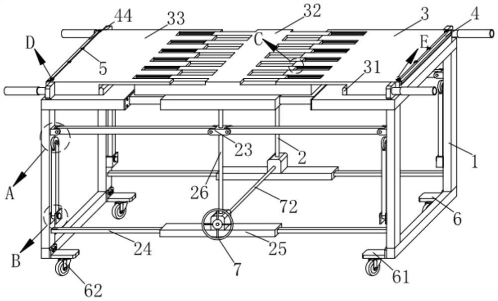
FIG. 1 is a schematic view of the overall structure of a cart-type surgical cart for conveniently transporting, loading and unloading a patient according to a preferred embodiment of the present invention;
FIG. 2 is an enlarged view of the part A shown in FIG. 1;
FIG. 3 is an enlarged view of the structure of the portion B shown in FIG. 1;
FIG. 4 is an enlarged view of the structure of the portion C shown in FIG. 1;
FIG. 5 is an enlarged view of the structure of the portion D shown in FIG. 1;
FIG. 6 is an enlarged view of the structure of the section E shown in FIG. 1;
FIG. 7 is a schematic view of a connection structure between the base plate and the expansion plate shown in FIG. 1;
FIG. 8 is an enlarged view of the structure of the portion F shown in FIG. 7;
FIG. 9 is a schematic view of the connection structure of the first fixing sleeve and the screw shown in FIG. 1;
fig. 10 is a schematic view of a connection structure of the mounting seat and the protrusion shown in fig. 6.
In the figure: 1. the adjustable bed comprises a bed body, 2, an adjusting structure, 21, a fixed seat, 22, a rotating rod, 23, an adjusting block, 24, a fixed rod, 25, a first fixed sleeve, 26, a screw rod, 3, an expansion structure, 31, a positioning plate, 32, a bottom plate, 33, an expansion plate, 34, a guide rod, 35, a limiting sheet, 36, a sliding chute, 37, a sliding rod, 4, a containing structure, 41, a rotating shaft, 42, a rolling roller, 43, a rotating belt, 44, a bottom pad, 45, a groove, 5, an installing structure, 51, an installing sheet, 52, an installing groove, 53, an installing seat, 54, a bulge, 55, a sliding block, 56, a spring, 6, a supporting structure, 61, a supporting plate, 62, a roller, 63, a second fixed sleeve, 64, a supporting rod, 65, a pulley, 66, a bolt, 7, a transmission structure, 71, a first bevel gear, 72, a rotating rod, 73, a second bevel gear, 74 and a rotating handle.
Detailed Description
In order to make the technical means, the creation characteristics, the achievement purposes and the effects of the invention easy to understand, the invention is further described with the specific embodiments.
As shown in fig. 1 to 10, the trolley-type surgical cart convenient for moving, loading and unloading patients according to the present invention includes a bed body 1, an adjusting structure 2 is installed on the bed body 1, a telescopic structure 3 is installed on the bed body 1, a storage structure 4 is installed inside the telescopic structure 3, an installation structure 5 is installed on the storage structure 4, a supporting structure 6 is installed on the bed body 1, and a transmission structure 7 is installed on the adjusting structure 2.
It is specific, it includes fixing base 21 to adjust structure 2, be two fixing bases 21 of parallel symmetry fixedly connected with on the bed body 1, two all rotate on the fixing base 21 and be connected with rotary rod 22, two rotary rod 22 is parallel symmetry and rotates jointly and is connected with regulating block 23, when needs are adjusted the bed body 1 according to patient's height, stimulates the regulating block 23 downwards, because rotary rod 22 is all installed at regulating block 23 both ends, and two rotary rods 22 all rotate through fixing base 21 and the bed body 1 and are connected, consequently stimulates the regulating block 23 downwards and can adjust the length of the bed body 1.
Specifically, be parallel symmetry fixedly connected with dead lever 24 on the bed body 1, two the common sliding connection of dead lever 24 other end has first fixed cover 25, through at 1 both ends installation dead lever 24 of the bed body, and two dead levers 24 respectively with first fixed cover 25 sliding connection, consequently can prevent the slope of the bed body 1, it is connected with lead screw 26 to rotate on the bed body 1, lead screw 26 and regulating block 23 threaded connection, then rotate lead screw 26, can better drive regulating block 23 and reciprocate.
Specifically, the telescopic structure 3 comprises positioning plates 31, two positioning plates 31 are fixedly connected to the bed body 1 in parallel and symmetrical relationship, the bottom plate 32 and the expansion plate 33 can be placed by installing the positioning plate 31 on the bed body 1, a bottom plate 32 is arranged on the bed body 1, two expansion plates 33 are slidably connected on the bottom plate 32 in parallel and symmetrical relation, the two ends of the bottom plate 32 are slidably connected with the telescopic plates 33, so that the patients with different heights can be adjusted, the two telescopic plates 33 are fixedly connected with the guide rods 34, by installing the guide bar 34 on the expansion plate 33, and slidably connecting the guide bar 34 and the bottom plate 32, therefore, the bottom plate 32 and the expansion plate 33 can be prevented from being separated, the two guide rods 34 are connected with the bottom plate 32 in a sliding mode, the two guide rods 34 are fixedly connected with the limiting pieces 35, and the guide rods 34 can be prevented from sliding out of the bottom plate 32 through the limiting pieces 35.
Specifically, the telescopic plate 33 is provided with a sliding groove 36, the bottom plate 32 is provided with a sliding rod 37, the sliding rod 37 is connected with the sliding groove 36 in a sliding manner, the telescopic plate 33 is provided with the sliding groove 36, and the bottom plate 32 is provided with the sliding rod 37, so that the bottom plate 32 and the telescopic plate 33 can be prevented from being dislocated and inclined by sliding the sliding groove 36 and the sliding rod 37.
It is specific, accomodate structure 4 includes pivot 41, two the expansion plate 33 is inside all to rotate and to be connected with two pivots 41, two equal fixedly connected with roll roller 42, two on the pivot 41 the rotatory area 43 is installed in the cooperation of roll roller 42, is connected with two pivot 41 through at expansion plate 33 internal rotation, and installs roll roller 42 in the pivot 41, and two roll roller 42 carry out the transmission to rotatory area 43, install heelpiece 44, two on the rotatory area 43 all be equipped with recess 45 on the expansion plate 33, then the pulling fixes heelpiece 44 on rotatory area 43, and heelpiece 44 pulls out through recess 45, consequently through installing heelpiece 44 on bottom plate 32 and expansion plate 33, protects patient, after pulling out the heelpiece 44 on both sides.
Specifically, mounting structure 5 is including installation piece 51, install installation piece 51 on the heelpiece 44, be equipped with mounting groove 52 on the installation piece 51, another install mount pad 53 on the heelpiece 44, sliding connection has arch 54 on mount pad 53, arch 54 and mounting groove 52 block through be equipped with mounting groove 52 on installation piece 51, sliding connection has arch 54 on mount pad 53, and consequently the block through arch 54 and mounting groove 52 can be fixed two heelpieces 44, places the automatic landing of heelpiece 44.
Specifically, the bottom end of the protrusion 54 is fixedly connected with a sliding block 55, a spring 56 is installed between the sliding block 55 and the mounting seat 53, and the protrusion 54 can be prevented from automatically sliding by the elastic force of the spring 56 installed between the sliding block 55 and the mounting seat 53, so that the two bottom cushions 44 are separated and dropped.
Concretely, bearing structure 6 includes backup pad 61, install a plurality of backup pads 61 on the bed body 1, it is a plurality of the equal fixedly connected with gyro wheel 62 in backup pad 61 bottom can carry out multi-angle movable with the bed body 1 through installing gyro wheel 62 in backup pad 61, the fixed cover 63 of a plurality of seconds of fixedly connected with on the bed body 1, it is connected with bracing piece 64 to rotate on the fixed cover 63 of second, it is connected with pulley 65 to rotate on the bracing piece 64, threaded connection has bolt 66 on the fixed cover 63 of second, when needs put down patient, not hard up bolt 66, can rotate bracing piece 64 is rotatory, then through pulley 65, prevents that bed body 1 from rotating, and it is fixed to lock through bolt 66 once more at last.
Specifically, the transmission structure 7 includes a first bevel gear 71, a first bevel gear 71 is fixedly connected to the screw rod 26, a rotating rod 72 is rotatably connected to the first fixing sleeve 25, a second bevel gear 73 is fixedly connected to the rotating rod 72, the first bevel gear 71 is engaged with the second bevel gear 73, a rotating handle 74 is fixedly connected to the rotating rod 72, and when the bed body 1 needs to be extended and retracted, the rotating rod 72 is rotated to drive the second bevel gear 73 on the rotating rod 72 to rotate, so that the first bevel gear 71 can be driven to rotate, and the screw rod 26 is driven to rotate to perform adjustment.
When the invention is used, when the bed body 1 is required to be adjusted according to the height of a patient, the adjusting block 23 is pulled downwards, because the two ends of the adjusting block 23 are both provided with the rotating rods 22, and the two rotating rods 22 are both rotatably connected with the bed body 1 through the fixing seats 21, the length of the bed body 1 can be adjusted by pulling the adjusting block 23 downwards, the fixing rods 24 are arranged at the two ends of the bed body 1, and the two fixing rods 24 are respectively and slidably connected with the first fixing sleeves 25, so that the bed body 1 can be prevented from inclining, then the screw rod 26 is rotated, the adjusting block 23 can be better driven to move up and down, the telescopic plates 33 are slidably connected at the two ends of the bottom plate 32, so that the invention can prevent the bottom plate 32 and the telescopic plates 33 from separating, the guide rods 34 can be prevented from sliding out of the bottom plate 32 through the limiting sheets 35, the bottom plate 32 and the expansion plate 33 can be placed by installing the positioning plate 31 on the bed body 1, since the sliding groove 36 is arranged on the expansion plate 33, the sliding rod 37 is arranged on the bottom plate 32, the bottom plate 32 and the expansion plate 33 can be prevented from being inclined by dislocation by sliding the sliding groove 36 and the sliding rod 37, two rotating shafts 41 are rotatably connected in the expansion plate 33, rolling rollers 42 are arranged on the rotating shafts 41, the two rolling rollers 42 drive the rotating belt 43, then the base pad 44 fixed on the rotating belt 43 is pulled, the base pad 44 is pulled out through the groove 45, therefore, the patient can be protected by installing the base pad 44 on the bottom plate 32 and the expansion plate 33, after the base pads 44 on both sides are pulled out, the mounting grooves 52 are arranged on the mounting pieces 51, the bulges 54 are slidably connected on the mounting seats 53, and therefore, the two base pads 44 can be fixed by the clamping of the bulges 54 and the mounting grooves 52, place the automatic landing of heelpiece 44, through the elasticity of installing the spring 56 between slider 55 and mount pad 53, can prevent protruding 54 self-sliding, cause two heelpieces 44 separately to drop, can carry out multi-angle mobility with the bed body 1 through the gyro wheel 62 of installing on backup pad 61, when needs put down patient, not hard up bolt 66, can rotate the bracing piece 64 rotation, then pass through pulley 65, prevent that the bed body 1 from rotating, it is fixed to lock through bolt 66 once more at last, when needs are flexible with the bed body 1, it drives the second bevel gear 73 rotation on the bull stick 72 to rotate bull stick 72, consequently, can drive first bevel gear 71 and rotate, thereby drive lead screw 26 and rotate and adjust.
It will be evident to those skilled in the art that the invention is not limited to the details of the foregoing illustrative embodiments, and that the present invention may be embodied in other specific forms without departing from the spirit or essential attributes thereof. The present embodiments are therefore to be considered in all respects as illustrative and not restrictive, the scope of the invention being indicated by the appended claims rather than by the foregoing description, and all changes which come within the meaning and range of equivalency of the claims are therefore intended to be embraced therein. Any reference sign in a claim should not be construed as limiting the claim concerned.
Furthermore, it should be understood that although the present description refers to embodiments, not every embodiment may contain only a single embodiment, and such description is for clarity only, and those skilled in the art should integrate the description, and the embodiments may be combined as appropriate to form other embodiments understood by those skilled in the art.
- 上一篇:一种医用注射器针头装配设备
- 下一篇:新生儿转运摇床