Intelligent ward data acquisition system and method based on Internet of things
阅读说明:本技术 一种基于物联网的智能病房数据采集系统及方法 (Intelligent ward data acquisition system and method based on Internet of things ) 是由 田甜 宗盈 黄娜 于 2021-08-06 设计创作,主要内容包括:本发明属于先进制造与自动化领域,并涉及先进制造工艺与装备领域,尤其涉及机器人领域中的先进服务机器人及自动化生产线技术领域,具体公开一种基于物联网的智能病房数据采集系统及其使用方法,包括采集系统,还包括与采集系统相配合的控制系统;采集系统包括设置在每个病房内的数据储存装置,还包括数据收集装置;数据收集装置包括移动平台,移动平台上设置有与数据储存装置相配合的文件收集装置和文件放置装置;移动平台上设置有摄像装置;移动平台内还设置有储物装置;本发明提供了一种可自动、高效采集数据的基于物联网的智能病房数据采集系统。(The invention belongs to the field of advanced manufacturing and automation, relates to the field of advanced manufacturing process and equipment, particularly relates to the technical field of advanced service robots and automatic production lines in the field of robots, and particularly discloses an intelligent ward data acquisition system based on the Internet of things and a use method thereof, wherein the intelligent ward data acquisition system comprises an acquisition system and a control system matched with the acquisition system; the acquisition system comprises a data storage device arranged in each ward and a data collection device; the data collecting device comprises a mobile platform, and a file collecting device and a file placing device which are matched with the data storage device are arranged on the mobile platform; the mobile platform is provided with a camera device; a storage device is also arranged in the mobile platform; the invention provides an intelligent ward data acquisition system based on the Internet of things, which can automatically and efficiently acquire data.)
1. An intelligent ward data acquisition system based on the Internet of things is characterized by comprising an acquisition system and a control system matched with the acquisition system; the acquisition system comprises a data storage device arranged in each ward and a data collection device; the data collection device comprises a mobile platform, and a file collection device and a file placement device which are matched with the data storage device are arranged on the mobile platform; the mobile platform is provided with a camera device; and a storage device is also arranged in the mobile platform.
2. The intelligent ward data acquisition system based on the internet of things as claimed in claim 1, wherein the data storage device comprises a clamping mechanism and further comprises a file storage mechanism matched with the clamping mechanism; the clamping mechanism comprises a clamping platform fixedly connected to the wall of the ward, and the cross section of the clamping platform is in a right trapezoid shape; the clamping platform comprises an inclined clamping surface; the clamping platform is provided with a clamp parallel to the clamping surface; the clamp comprises a pair of first clamping plates arranged on a clamping surface, and each first clamping plate is connected with the clamping surface in a sliding manner; the left end and the right end of the clamping surface are fixedly connected with a first supporting plate; a plurality of pressure springs are arranged between the first supporting plate and the first clamping plate, and each pressure spring is parallel to the clamping surface; the pair of first clamping plates is also connected with a clamping plate opening mechanism.
3. The intelligent ward data acquisition system based on the internet of things as claimed in claim 2, wherein the splint opening mechanism comprises a first sliding groove formed in the clamping platform, and the length direction of the first sliding groove is perpendicular to the length direction of the first splint; a pair of first sliding plates are arranged in the first sliding groove, and each first sliding plate is fixedly connected with a first clamping plate; one end of each first sliding plate adjacent to the other first sliding plate is provided with an inclined sliding connection surface, and each sliding connection surface is vertical to the clamping surface; a wedge-shaped block is further arranged in the first sliding chute, and the wedge-shaped block is arranged between the two sliding connection surfaces and is in sliding connection with the sliding connection surfaces; a second sliding groove perpendicular to the first sliding groove is further formed in the first sliding groove, and a first limiting sliding block fixedly connected with the wedge block is arranged in the second sliding groove; a first connecting rod is hinged to the wedge-shaped block, and a long rod-shaped labor-saving handle is hinged to the other end of the first connecting rod; one end of the labor-saving handle is hinged with a first fixed shaft, and the first fixed shaft is fixedly connected with the clamping platform; the other end of the labor-saving handle is arranged outside the clamping platform.
4. The internet of things-based intelligent ward data collection system of claim 3, wherein the file storage mechanism comprises a third support plate disposed between a pair of first clamping plates; the top of the third supporting plate is provided with an electric clamp, the electric clamp comprises a second clamping plate parallel to the third supporting plate, and a first electric telescopic rod is connected to the second clamping plate; the first electric telescopic rod is fixedly connected to the third supporting plate, and the first electric telescopic rod and the third supporting plate are arranged at an acute angle; the bottom end of the third supporting plate is provided with a switch connected with the first electric telescopic rod; the top of the clamping platform is provided with a first groove.
5. The intelligent ward data acquisition system based on the internet of things as claimed in claim 4, wherein the file collection device comprises a first pressing block matched with a switch, and a vertical second electric telescopic rod is connected below the first pressing block; the first pressing block is also connected with a lifting ladder, and one end of the lifting ladder, which is far away from the first pressing block, is provided with a collecting box; the elevator comprises a head end inclined plate, a tail end inclined plate and a plurality of middle inclined plates arranged between the head end inclined plate and the tail end inclined plate; the top end of the head end inclined plate is fixedly connected with the first pressing block, and the head end inclined plate comprises a sliding block fixedly connected with the bottom of the head end inclined plate; each middle inclined plate comprises a sliding rail which is connected with the sliding block in a sliding manner, the sliding rails are vertically arranged on two sides of the middle inclined plate, and each middle inclined plate comprises a sliding block which is fixedly connected to the bottom of the middle inclined plate; the bottom of tail end swash plate has linked firmly the slider, it has the slide rail that is connected with the slider on the tail end swash plate to link firmly on the collection box.
6. The intelligent ward data acquisition system based on the internet of things as claimed in claim 5, wherein a pair of door panels are hinged to the top end of the collection box, and an automatic closing mechanism is arranged between each door panel and the collection box; each door plate is connected with a synchronous opening mechanism; the synchronous opening mechanism comprises a first connecting rope fixedly connected with the door plate, and the other end of the first connecting rope is fixedly connected with a sliding block on the tail end inclined plate; the synchronous opening mechanism also comprises a pulley block connected with the first connecting rope, the pulley block comprises a first fixed pulley arranged on one side of the door plate, and the first fixed pulley is arranged above the collecting box; the pulley block also comprises a second fixed pulley connected to the collecting box, and the second fixed pulley is positioned at the bottom of the sliding rail on the collecting box; the pulley block also comprises a diverting pulley arranged between the first fixed pulley and the second fixed pulley.
7. The intelligent ward data acquisition system based on the internet of things as claimed in claim 6, wherein the collecting box is of a square structure, a paper feeding mechanism is further arranged in the collecting box, and the paper feeding mechanism comprises a second supporting plate which is horizontally arranged; the second support plate is fixedly connected to the wall of the collecting box adjacent to the elevator, third sliding grooves are formed in the left side and the right side of the second support plate, and the third sliding grooves are formed above the second support plate; the third chute is connected with a conveyer; the conveyor comprises a second sliding plate arranged in a third sliding groove, and the second sliding plate is connected with a horizontal third electric telescopic rod; the second sliding plate is connected with a first rotating shaft and a second rotating shaft, annular belts are sleeved on the first rotating shaft and the second rotating shaft, and soft extrusion layers are arranged on the outer annular surfaces of the annular belts.
8. The intelligent ward data acquisition system based on the internet of things as claimed in claim 7, wherein the file placing device comprises a second pressing block matched with a switch, and a vertical fourth electric telescopic rod is connected below the second pressing block; the second pressing block is connected with a paper placing mechanism, the paper placing mechanism comprises a first rotating shaft hinged with the second pressing block, and one end of the first rotating shaft is connected with a first motor; the outer peripheral surface of the first rotating shaft is connected with a connecting plate, and the connecting plate is connected with a paper extractor; the file placing device further comprises a paper storage box matched with the paper taking device, the paper storage box is of a square structure, a vertical groove is formed in the wall, close to the first rotating shaft, of the paper storage box, and the vertical groove is matched with the connecting plate and is arranged under the connecting plate.
9. The intelligent ward data acquisition system based on the internet of things as claimed in claim 8, wherein the paper picker comprises a pair of paper-picking plates rotatably connected at two sides of the connecting plate, the length direction of the paper-picking plates is consistent with that of the paper storage box, and a horizontal second connecting rod is fixedly connected between the pair of paper-picking plates; the bottom end of each paper taking plate is provided with a pressure sensor; the bottom end of each paper taking plate is provided with an air suction port, an air suction channel communicated with the air suction port is arranged in the connecting plate, and the connecting plate is fixedly connected with a suction fan communicated with the air suction channel; one of the paper taking plates is fixedly connected with a first driven gear, the first driven gear is connected with a first driving gear in a meshed mode, the first driving gear is connected with a second motor, and the second motor is fixedly connected with a connecting plate; the control system comprises a control module, and the second electric telescopic rod, the third electric telescopic rod, the fourth electric telescopic rod, the first motor and the second motor are all connected with the control module.
10. The method for an intelligent ward data collection system based on internet of things of any one of claims 1 to 9, comprising the steps of:
step 1, monitoring ward instrument data; the control module controls the mobile platform to patrol in each ward according to a set route; the control module controls and adjusts the camera device to shoot and compare data, images and the like displayed by instruments in the ward;
step 2, measuring and recording the patient data; when the medical staff checks the body temperature, the blood pressure and other physical signs of the patient, the labor-saving handle is pressed down to take the third supporting plate out of the data storage device, and the measured physical sign data of the patient are filled in the paper of the third supporting plate;
step 3, storing the patient data; the control module controls the mobile platform to move to the front of a data storage device in a ward according to a set route; the control module controls the camera device to adjust the position, and takes pictures and uploads the pictures to the paper on the third supporting plate; the control module controls the mobile platform to move, and the file collection device moves to the middle position below the data storage device; the control module controls the file collecting device to collect paper;
step 4, adding paper; after the paper is collected, the control module controls the mobile platform to move, and the file placing device moves to the middle position below the data storage device; the control module controls the file placing device to place the paper on the third supporting plate.
Technical Field
The invention belongs to the field of advanced manufacturing and automation, relates to the field of advanced manufacturing processes and equipment, particularly relates to the technical field of advanced service robots and automatic production lines in the robot field, and particularly relates to an intelligent ward data acquisition system based on the Internet of things and a method of the intelligent ward data acquisition system based on the Internet of things.
Background
The physical condition of the patient in the whole treatment process can be mastered in detail by acquiring the ward data, the analysis of the patient's condition is facilitated, and the abnormal condition of the patient can be found in time; through data acquisition, a large amount of treatment information of patients can be stored, classification analysis of various disease information is facilitated, and medical development is promoted. The collection of ward data is a very tedious task, and each inpatient generates a large amount of data each day. At present, the ward data is acquired manually, medical staff need to measure the body temperature, blood pressure and other information of a patient every day and check the reading of a monitoring instrument used by the patient, the medical staff cannot check the data of the monitoring instrument frequently due to limited manpower, and the medical staff cannot store and arrange the information, so that the measured data are not fully utilized; the conventional articles (such as a thermometer, a drainage bag and the like) in a ward are prone to loss, and the loss of the articles is manually counted and replaced at present, so that the mode is low in efficiency and consumes more manpower.
Disclosure of Invention
The invention aims to provide an intelligent ward data acquisition system based on the Internet of things, which can automatically and efficiently acquire data, and a method of the intelligent ward data acquisition system based on the Internet of things.
Based on the purpose, the invention adopts the following technical scheme:
an intelligent ward data acquisition system based on the Internet of things comprises an acquisition system and a control system matched with the acquisition system; the acquisition system comprises a data storage device arranged in each ward and a data collection device; the data collecting device comprises a mobile platform, and a file collecting device and a file placing device which are matched with the data storage device are arranged on the mobile platform; the mobile platform is provided with a camera device; a storage device is further arranged in the mobile platform.
Furthermore, the data storage device comprises a clamping mechanism and a file storage mechanism matched with the clamping mechanism; the clamping mechanism comprises a clamping platform fixedly connected to the wall of the ward, and the cross section of the clamping platform is in a right trapezoid shape; the height of the cross section of the clamping platform is attached to the wall, and the upper bottom of the cross section of the clamping platform is shorter than the lower bottom; the clamping platform comprises an inclined clamping surface, and the top end of the clamping surface is closer to the wall than the bottom end of the clamping surface; the clamping platform is provided with a clamp parallel to the clamping surface; the clamp holder comprises a pair of first clamp plates arranged on a clamping surface, each first clamp plate is vertical to the clamping surface, and each first clamp plate is connected with the clamping surface in a sliding manner; the length direction of each first clamping plate is consistent with that of the clamping surface, and the length direction of the clamping surface is the direction of the bevel edge of the cross section of the clamping platform; the left end and the right end of the clamping surface are fixedly connected with first supporting plates parallel to the first clamping plates, and the pair of first clamping plates are arranged between the pair of first supporting plates; a plurality of pressure springs are arranged between the first supporting plate and the first clamping plate, and each pressure spring is parallel to the clamping surface; the pair of first clamping plates is also connected with a clamping plate opening mechanism.
Further, the clamping plate opening mechanism comprises a first sliding groove formed in the clamping platform, and the length direction of the first sliding groove is perpendicular to the length direction of the first clamping plate; a pair of first sliding plates are arranged in the first sliding groove, and each first sliding plate is fixedly connected with the first clamping plate; one end of each first sliding plate adjacent to the other first sliding plate is provided with an inclined sliding connection surface, and each sliding connection surface is vertical to the clamping surface; a wedge-shaped block is also arranged in the first sliding chute, the wedge-shaped block is arranged between the two sliding connection surfaces and is in sliding connection with the sliding connection surfaces, and the left side and the right side of the wedge-shaped block are provided with two surfaces parallel to the sliding connection surfaces; a second sliding groove perpendicular to the first sliding groove is further formed in the first sliding groove, and a first limiting sliding block fixedly connected with the wedge block is arranged in the second sliding groove; a first connecting rod is hinged on the wedge-shaped block, the bottom end of the first connecting rod is hinged with the wedge-shaped block, and the top end of the first connecting rod is hinged with a long rod-shaped labor-saving handle; a first cavity communicated with the first chute is formed in the clamping platform, and the labor-saving handle is arranged in the first cavity; one end of the labor-saving handle is hinged with a first fixed shaft, the first fixed shaft is perpendicular to the labor-saving handle, and the first fixed shaft is fixedly connected with the clamping platform; the other end of the labor-saving handle is arranged outside the clamping platform. The labor-saving handle, the first connecting rod, the wedge-shaped block, the first sliding groove and the first sliding plate are all parallel to the clamping surface.
Further, the document storage mechanism includes a third support plate disposed between the pair of first clamping plates; the top of the third supporting plate is provided with an electric clamp which comprises a second clamping plate parallel to the third supporting plate, and the second clamping plate is connected with a first electric telescopic rod; the first electric telescopic rod is fixedly connected to the third supporting plate, the first electric telescopic rod and the third supporting plate are arranged at an acute angle, and the extending direction of the first electric telescopic rod extends obliquely upwards; the bottom end of the third supporting plate is provided with a switch connected with the first electric telescopic rod, and the switch is a non-self-locking switch; first recess has been seted up at the top of centre gripping platform, and first recess communicates the top and the third backup pad of centre gripping platform.
Furthermore, the file collecting device comprises a first pressing block matched with the switch, the first pressing block is arranged below the switch, a vertical second electric telescopic rod is connected below the first pressing block, and the bottom end of the second electric telescopic rod is fixedly connected with the moving platform; the first pressing block is also connected with a lifting ladder, and one end of the lifting ladder, which is far away from the first pressing block, is provided with a collecting box; the elevator comprises a head end inclined plate, a tail end inclined plate and a plurality of middle inclined plates, wherein the head end inclined plate, the tail end inclined plate and the middle inclined plates are parallel to each other and are obliquely arranged; the top end of the head end inclined plate is fixedly connected with the first pressing block, and the head end inclined plate comprises a sliding block fixedly connected with the bottom of the head end inclined plate; each middle inclined plate comprises a sliding rail which is connected with the sliding block in a sliding manner, the sliding rails are vertically arranged on two sides of the middle inclined plate, and each middle inclined plate comprises a sliding block which is fixedly connected with the bottom of the middle inclined plate; the tail end swash plate is the same with middle swash plate structure, and the top of tail end swash plate has linked firmly the slide rail, the bottom has linked firmly the slider, has linked firmly the slide rail that is connected with the slider on the tail end swash plate on the collection box.
Furthermore, a pair of symmetrical door plates is hinged at the top end of the collecting box, and an automatic closing mechanism is arranged between each door plate and the collecting box; each door plate is connected with a synchronous opening mechanism; the synchronous opening mechanism comprises a first connecting rope, one end of the first connecting rope is fixedly connected with the door panel, and the other end of the first connecting rope is fixedly connected with a sliding block on the tail end inclined plate; the synchronous opening mechanism also comprises a pulley block which is connected with the first connecting rope in a sliding way, the pulley block comprises a first fixed pulley arranged on one side of the door plate, and the first fixed pulley is arranged above the collecting box; the pulley block also comprises a second fixed pulley connected to the collecting box, and the height position of the second fixed pulley is positioned at the bottom of the sliding rail on the collecting box; the pulley block also comprises a steering pulley arranged between the first fixed pulley and the second fixed pulley; the shafts of the first fixed pulley, the second fixed pulley and the steering pulley are fixedly connected with the collecting box.
Furthermore, the collecting box is of a square structure, and a paper feeding mechanism is also arranged in the collecting box and comprises a second supporting plate which is horizontally arranged; the second support plate is fixedly connected to the wall of the collecting box adjacent to the elevator, the left side and the right side of the second support plate are provided with horizontal third sliding chutes, the third sliding chutes are formed in the walls of the left side and the right side of the collecting box, and the third sliding chutes are arranged above the second support plate; each third sliding chute is connected with a conveyor, each conveyor comprises a second sliding plate arranged in the third sliding chute, each second sliding plate is connected with a horizontal third electric telescopic rod, and the length direction of each third electric telescopic rod is consistent with the length direction of the third sliding chute; the second sliding plate is connected with a first rotating shaft and a second rotating shaft, and the first rotating shaft is connected with a fourth motor; the first rotating shaft and the second rotating shaft are sleeved with annular belts which are arranged above the second supporting plate and are parallel to the second supporting plate; and a soft extrusion layer is arranged on the outer annular surface of the annular belt.
Furthermore, the file placing device comprises a second pressing block matched with the switch, a vertical fourth electric telescopic rod is connected below the second pressing block, and the bottom end of the fourth electric telescopic rod is fixedly connected with the moving platform; the second pressing block is connected with a paper placing mechanism, the paper placing mechanism comprises a first rotating shaft hinged with the second pressing block, the first rotating shaft is horizontally arranged, the length direction of the first rotating shaft is the left-right direction, one end of the first rotating shaft is connected with a first motor, and the first motor is fixedly connected with the second pressing block; the outer peripheral surface of the first rotating shaft is fixedly connected with a connecting plate, and a paper taking device is connected onto the connecting plate; the file placing device further comprises a paper storage box matched with the paper taking device, the paper storage box is of a square structure with an opening at the top end, a vertical groove is formed in the wall (the wall on the front side) of the paper storage box close to the first rotating shaft, the paper storage box is communicated with the inside and the outside of the paper storage box through the vertical groove, and the vertical groove is matched with the connecting plate and is arranged under the connecting plate.
Furthermore, the paper taking device comprises a pair of paper taking plates which are rotatably connected with each other on two sides of the connecting plate, the paper taking plates are of long plate structures, the length direction of the paper taking plates is consistent with that of the paper storage box, and the length direction of the paper storage box is the front-back direction; a horizontal second connecting rod is fixedly connected between the pair of paper taking plates; the bottom end of each paper taking plate is provided with a pressure sensor; the bottom end of each paper taking plate is provided with an air suction port, air suction channels communicated with the air suction ports are arranged in the paper taking plates and the connecting plates, and the connecting plates are fixedly connected with suction fans communicated with the air suction channels; one of the paper taking plates is fixedly connected with a first driven gear, the first driven gear is meshed with a first driving gear, the first driving gear is connected with a second motor, and the second motor is fixedly connected with a connecting plate. The upper part of the paper storage box is provided with a horizontal electric door.
Furthermore, the control system comprises a control module, and the second electric telescopic rod, the third electric telescopic rod, the fourth electric telescopic rod, the first motor, the second motor, the pressure sensor and the electric door are all connected with the control module.
Furthermore, the storage device comprises a row of storage drawers arranged in the mobile platform, each storage drawer is horizontally arranged, and each storage drawer is in sliding connection with the mobile platform; each storage drawer is connected with a first locking mechanism and a second locking mechanism; the first locking mechanism comprises a plurality of first springs, and a first spring is arranged between each storage drawer and the movable platform; each first spring is horizontally arranged and is consistent with the sliding direction of the storage drawer, the length direction of the storage drawer is consistent with the sliding direction of the storage drawer, and the storage drawer slides along the front and back directions of the moving platform; the first locking mechanism also includes a spool retractor coupled to each of the storage drawers.
Furthermore, the reel winding and unwinding device comprises third pulleys connected with the tail end of each storage drawer, each third pulley is arranged in the middle of the storage drawer in the width direction, and each third pulley is horizontally arranged; a pair of symmetrical tensioning pulleys is arranged on each of the two sides of each third pulley, and each tensioning pulley and the third pulleys are located in the same horizontal plane; a plurality of third pulleys and the tensioning wheel are connected with a second connecting rope which is horizontally arranged; one end of the second connecting rope is connected with a reel, and the reel is connected with a third motor which is coaxial with the reel and is vertically arranged; the other end of the second connecting rope is fixedly connected with the moving platform; the third motor is connected with the coded lock, and the third motor and the coded lock are both connected with the control module.
Furthermore, the second locking mechanism comprises a locking device, the locking device comprises a horizontal rod fixedly connected to the tail end of the storage drawer, and the length direction of the horizontal rod is consistent with the width direction of the storage drawer; the locking device also comprises a horizontal plate arranged above the horizontal rod, a vertical plate is fixedly connected onto the horizontal plate, and the horizontal rod is arranged between the vertical plate and the storage drawer; a pair of vertically downward supporting rods is fixedly connected to the left side and the right side of the horizontal plate, a horizontal third connecting rod is fixedly connected to each supporting rod, a barrel-shaped elastic rod is sleeved on each third connecting rod, each elastic rod is horizontally arranged, and the length directions of the elastic rods and the third connecting rods are consistent with the length direction of the storage drawer; a tension spring is arranged between each third connecting rod and the elastic rod, and the length direction of each tension spring is consistent with that of the elastic rod; one ends of the two elastic rods, which are far away from the third connecting rod, are fixedly connected with a horizontal second fixed shaft, the second fixed shaft is perpendicular to the elastic rods, and a vertical locking plate is hinged to the second fixed shaft; the horizontal rod is arranged between the locking plate and the vertical plate; the locking plate is arranged below the horizontal plate, one side of the locking plate close to the vertical plate is provided with a stop block, and the stop block is fixedly connected with the horizontal plate; the horizontal plates are connected with lifters. The elastic rod is fixedly connected with a first magnet, and the locking plate is provided with a second magnet which is attracted with the first magnet.
Furthermore, the lifter comprises a lever group, one end of the lever group is fixedly connected with the horizontal plate, and the other end of the lever group is connected with an elastic button; the lever group comprises a fourth connecting rod fixedly connected with the top end of the horizontal plate, and the fourth connecting rod is vertically arranged; the top end of the fourth connecting rod is hinged with a fifth connecting rod, the other end of the fifth connecting rod is hinged with a first lever, a horizontal third fixing shaft is rotatably connected to the middle position of the first lever, and the third fixing shaft is vertical to the length direction of the first lever; the length direction of the first lever is consistent with the width direction of the storage drawer; a sixth connecting rod is hinged to one end, far away from the third connecting rod, of the first lever, a second lever is hinged to the other end of the sixth connecting rod, the length direction of the second lever is consistent with the length direction of the storage drawer, and a horizontal fourth fixing shaft is rotatably connected to the middle position of the second lever; the length direction of the fourth fixed shaft is vertical to that of the second lever; a seventh connecting rod is hinged to one end, away from the first lever, of the second lever, a third lever is hinged to the other end of the seventh connecting rod, the length direction of the third lever is consistent with that of the second lever, a fifth fixing shaft is rotatably connected to the middle of the third lever, and the fifth fixing shaft is parallel to the fourth fixing shaft; the elastic button is arranged at one end of the third lever far away from the second lever. The third fixed shaft, the fourth fixed shaft and the fifth fixed shaft are fixedly connected with the moving platform; the second lever is arranged above the first lever, the third lever is arranged above the second lever, and the elastic button is arranged above the third lever. The length of the first lever of the second locking mechanism connected to each storage drawer is different, and the length of the first lever is set according to the transverse distance (the distance in the width direction of the storage drawer) between the horizontal plate of each second locking mechanism and the elastic button corresponding to the horizontal plate.
The method of the intelligent ward data acquisition system based on the Internet of things comprises the following steps:
step 1, monitoring ward instrument data; the control module controls the mobile platform to patrol in each ward according to a set route; the control module controls and adjusts the camera device to shoot and compare data, images and the like displayed by instruments in the ward.
Step 2, measuring and recording the patient data; when the medical staff checks the body temperature, the blood pressure and other physical signs of the patient, the third supporting plate is taken down from the data storage device by pressing down the labor-saving handle, and the measured physical sign data of the patient are filled in the paper of the third supporting plate.
Step 3, storing the patient data; the control module controls the mobile platform to move to the front of a data storage device in a ward according to a set route; the control module controls the camera device to adjust the position, and takes pictures and uploads the pictures to the paper on the third supporting plate; the control module controls the mobile platform to move, and the file collection device moves to the middle position below the data storage device; the control module controls the document collection device to collect the paper.
Step 4, adding paper; after the paper is collected, the control module controls the mobile platform to move, and the file placing device moves to the middle position below the data storage device; the control module controls the file placing device to place the paper on the third supporting plate.
Compared with the prior art, the invention has the following beneficial effects:
1. the file storage mechanism can clamp and store paper with patient data, and the clamping mechanism can clamp and fix the file storage mechanism, so that the paper is stored in a standardized mode at a fixed position, and a data collection device can collect the patient data conveniently. The inclined arrangement of the clamping surface of the clamping platform can enable paper to incline, so that the paper is attached to the third supporting plate under the action of gravity and is kept stable, and the paper is convenient to collect by the file collecting device. When the medical staff measures the body temperature, blood pressure and other data of the patient, the file storage mechanism can be taken down, and the data obtained by measuring each patient is filled into the paper on the file storage mechanism. The clamping plate opening mechanism can facilitate medical care to open the first clamping plate, and is convenient for taking, placing and storing the file.
2. The labor-saving handle of the clamp plate opening mechanism is pressed downwards, so that the labor-saving handle drives the wedge block to move downwards, and the wedge block moves downwards to drive the two first sliding plates to move backwards, so that the first clamp plate is opened. The labor-saving handle, the first connecting rod, the wedge block, the first sliding groove and the first sliding plate are all arranged inside the clamping platform, so that the structure of the clamping mechanism is more compact, and the occupied space is reduced.
3. The second clamping plate of the file storage mechanism is connected with the first electric telescopic rod, and the first electric telescopic rod is obliquely arranged; when making electronic clamp open, first electric telescopic handle can drive second splint rebound, makes things convenient for file placer to put the paper between third backup pad and the second splint, guarantees file placer steady operation.
4. The second electric telescopic rod of the file collecting device can drive the first pressing block to ascend, so that the first pressing block presses down the switch, the first electric telescopic rod extends, and paper automatically slides down. The first pressing block can drive the head end inclined plate to ascend, the head end inclined plate can drive the middle inclined plate and the tail end inclined plate to ascend through the sliding block and the sliding rail, finally the head end inclined plate, the tail end inclined plate and the middle inclined plate form an inclined sliding plate, and paper can slide into the collecting box through the head end inclined plate, the tail end inclined plate and the middle inclined plate.
5. The door plate can seal the top end of the collecting box to protect the interior of the collecting box from being polluted; the automatic closing mechanism can keep the collecting box in a closed state and can also make the collecting box have a tendency of closing when the collecting box is opened. The synchronous opening mechanism can enable the door plate to be automatically opened when paper enters the collecting box; the first connecting rope is connected with the slider of the tail end inclined plate through the pulley block, and when the tail end inclined plate ascends, the first connecting rope can drive the door plate to be automatically opened, so that paper enters the collecting box. And the second fixed pulley is arranged at the bottom of the sliding rail on the collecting box, so that when the sliding block of the tail end inclined plate ascends, the first connecting rope is pulled up, and the door plate is opened. After the paper enters the collecting box, the elevator is reset, and the automatic closing mechanism can drive the door plate to be automatically closed.
6. The paper feeding mechanism can enable paper to completely enter the collecting box, so that the paper can be smoothly paved at the bottom of the collecting box, and the paper is convenient to arrange neatly. When the paper fails to completely enter the collecting box under the action of gravity, the paper is obliquely laid on the wall of the front side of the collecting box, the third electric telescopic rod extends to enable the conveyor to move to the second supporting plate, the paper is clamped on the second supporting plate by the extrusion layer, the fourth motor can drive the first rotating shaft to rotate so as to drive the extrusion layer to rotate, and the paper is conveyed backwards by the extrusion layer to the bottom end of the collecting box when the paper completely falls into the collecting box.
7. The file placer can be put the paper to file storage mechanism automatically, when making medical personnel take notes patient's data, can directly take off the third backup pad and take off and take notes, need not medical personnel and put into the file storage mechanism with the paper again, and reducible medical personnel's work load improves data collection's efficiency. The fourth electric telescopic rod can lift the second pressing block to be in contact with the switch, the electric clamp is opened, and the paper extractor can take out paper from the paper storage box; the first motor can drive the first rotating shaft to rotate, so that the paper taking device rotates to the third supporting plate, the position of the paper is adjusted, and the paper is conveniently clamped on the third supporting plate by the electric clamp.
8. The paper taking device sucks up paper by using the paper taking plate through negative pressure, and the paper taking plate is placed above the paper, so that the paper is convenient to take; the second motor is connected with the first driving gear and the second driven gear, the rotation angle of the paper taking plate can be adjusted, and paper is placed on the first supporting plate, so that the paper can be conveniently clamped by the electric clamp; the fan can adjust the wind power and further adjust the suction force, so that the paper is stably adsorbed. The electrically operated door can prevent sundries from entering the paper storage box.
9. The storage device can be convenient for medical personnel to obtain articles commonly used from the mobile platform, and the medical personnel can replace some damaged articles in time and can count the loss condition of the articles commonly used. The first spring of the first locking mechanism can enable the storage drawer to keep the trend of opening, and the reel is connected with the second connecting rope, the third pulley and the tensioning pulley and can pull the storage drawer tightly to enable the storage drawer to keep the closed state; the storage drawers are connected to the same second connecting rope, so that the reel can act on any storage drawer when the second connecting rope is wound and unwound, and the winding and unwinding of any storage drawer are completed; the coded lock controls the reel to be wound and unwound, so that the phenomenon that non-working personnel randomly open the storage drawer can be avoided. The second locking mechanisms can enable the storage drawers to be kept in a locking state, and a button of each second locking mechanism corresponds to one storage drawer and can separately control different storage drawers; the first locking mechanism is matched with the second locking mechanism, so that the storage drawers can be controlled by the same coded lock, and the elastic buttons can be used for controlling the opening and closing of the specific storage drawer.
10. The elastic button can control the locking device to lift through the lever set, and operation is convenient. The horizontal pole setting of locking ware is between lock board and vertical board, and the accessible blocks the horizontal pole and then makes the storage drawer keep the state of closing. After the elastic button is pressed down, the lever group drives the horizontal plate to ascend, the horizontal plate drives the supporting rod, the third connecting rod, the elastic rod, the second fixed shaft and the locking plate to ascend, and after the bottom end of the locking plate ascends to the position above the horizontal rod, the tension spring compresses and drives the elastic rod, the second fixed shaft and the locking plate to move towards the supporting rod; after the elastic button is loosened, the horizontal plate moves downwards under the action of self gravity and drives the locking plate to move downwards, the locking plate stops after moving downwards to the horizontal rod, the horizontal rod is unlocked, and the first locking mechanism can control the storage drawer to be unlocked to be opened and closed. The dog can prevent that the locking plate bottom from rotating to the direction that is close to storage drawer, makes the locking plate can stably block the horizontal pole and remove. First magnet and second magnet attract each other can make the lock plate keep vertical state when descending, can stably be blockked by the horizon bar when making the lock plate descend, guarantees to press the elastic button after, the horizon bar can be by the unblock smoothly.
11. The control module can enable all devices of the acquisition system to automatically and orderly work by controlling the second electric telescopic rod, the third electric telescopic rod, the fourth electric telescopic rod, the first motor, the second motor, the third motor, the pressure sensor, the electric door and the reel.
In conclusion, the data storage device of the invention can facilitate medical personnel to standardize, arrange and store the patient data in the ward. The file collection device can automatically collect data on the data storage device; the first pressing block of the file collecting device is matched with a switch of the electric clamp, so that paper with data can automatically fall into the collecting box; the paper feeding mechanism can further arrange the paper to ensure that the paper is automatically and flatly laid at the bottom end of the collecting box; the synchronous opening mechanism and the automatic closing mechanism can enable the door plate to be matched with the elevator to automatically open and close the collecting box. The file placing device can automatically place paper on the data storage device, so that the workload of medical personnel is reduced; the second pressing block of the file placing device can be matched with a switch of the electric clamp, so that the electric clamp can be automatically opened, and the first motor is matched with the paper taking device, so that paper can be automatically taken and placed. The camera device can automatically patrol wards, monitor instruments in each ward and strengthen the collection of patient data. The storage device can be convenient for medical personnel to take out common articles. The invention can automatically patrol a ward, collect ward instrument data, automatically collect daily physical sign data of a patient, and automatically keep and file files, and belongs to the technical field of intelligent manufacturing.
Drawings
FIG. 1 is a schematic view of example 1 of the present invention;
FIG. 2 is a side view of a data storage device according to embodiment 1 of the present invention;
FIG. 3 is a front view of a memory device according to embodiment 1 of the present invention;
FIG. 4 is a schematic view of a chucking mechanism according to embodiment 1 of the present invention;
fig. 5 is a schematic structural view of a splint opening mechanism according to embodiment 1 of the present invention;
FIG. 6 is an enlarged view of a portion of FIG. 5;
FIG. 7 is a schematic view showing the connection between the first slide plate and the first clamp plate according to embodiment 1 of the present invention;
FIG. 8 is a side view of a document storage mechanism according to embodiment 1 of the present invention;
FIG. 9 is a schematic view of a document collection apparatus according to embodiment 1 of the present invention;
FIG. 10 is an enlarged view of a portion of FIG. 9;
FIG. 11 is a schematic view of a synchrotilt opening mechanism according to embodiment 1 of the present invention;
FIG. 12 is an enlarged view of a portion of FIG. 11;
fig. 13 is a schematic view of an automatic closing mechanism of embodiment 1 of the present invention;
FIG. 14 is a schematic view of a paper feeding mechanism according to embodiment 1 of the present invention;
FIG. 15 is an enlarged partial view of FIG. 13;
fig. 16 is a schematic view of a conveyor according to embodiment 1 of the present invention;
FIG. 17 is a schematic view of a document placing apparatus according to embodiment 1 of the present invention;
FIG. 18 is an enlarged partial view of FIG. 16;
fig. 19 is a schematic view of a paper picker according to embodiment 1 of the present invention;
FIG. 20 is a schematic view of a paper extraction panel according to example 1 of the present invention;
FIG. 21 is a schematic view of an organizing mechanism of embodiment 3 of the present invention;
FIG. 22 is a schematic view showing example 4 of the present invention;
fig. 23 is a schematic view of a storage device according to embodiment 4 of the present invention;
fig. 24 is a schematic view of a first locking mechanism of embodiment 4 of the invention;
FIG. 25 is an enlarged partial view of FIG. 22;
FIG. 26 is an enlarged partial view of FIG. 23;
fig. 27 is a schematic view showing the connection of the third connecting rod and the resilient lever according to embodiment 4 of the present invention;
fig. 28 is a schematic view of a lever set according to embodiment 4 of the present invention.
In the figure: the file storage device comprises a data storage device 1, a moving platform 2, a file collecting device 3, a file placing device 4, a camera device 5, a storage device 6, a clamping platform 101, a wall 7, a clamping surface 102, a first clamping plate 103, a first supporting plate 104, a pressure spring 105, a first sliding chute 106, a first sliding plate 107, a fourth sliding chute 108, a connecting block 109, a sliding connecting surface 110, a wedge block 111, a second sliding chute 112, a first limit slider 113, a first connecting rod 114, a labor-saving handle 115, a first cavity 116, a first fixed shaft 117, a third supporting plate 118, a second clamping plate 119, a first electric telescopic rod 120, a switch 121, a first groove 122, a communicating groove 123, a first pressing block 301, a second electric telescopic rod 302, a collecting box 303, a head end inclined plate 304, a tail end inclined plate 305, a middle inclined plate 306, a sliding block 307, a sliding rail 308, a door plate 309, a second groove 310, a second spring 311, a first connecting rope 312, a first fixed pulley 313, a second sliding plate 103, a second sliding plate 108, a second, A second fixed pulley 314, a diverting pulley 315, a second support plate 316, a third sliding chute 317, a second sliding plate 318, a third electric telescopic rod 319, a first rotating shaft 320, a second rotating shaft 321, a fourth motor 322, a second driving gear 323, a second driven gear 324, an annular belt 325, a squeezing layer 326, a sliding plate 327, a second limit slider, a fifth sliding chute 329, a fifth electric telescopic rod, a second pressing block 401, a fourth electric telescopic rod 402, a first rotating shaft 403, a first motor 404, a connecting plate 405, a paper storage box 406, a vertical slot 407, a paper taking plate 408, a second connecting rod 409, a pressure sensor 410, an air suction port 411, an air suction channel 412, a suction fan 413, a first driven gear 414, a first driving gear 415, a second motor 416, an electric door 417, a reel drawer 601, a first storage spring 602, a third pulley 603, a tensioning pulley 604, a second connecting rope 605, a reel 606, a third motor 607, a fourth driven gear 329, a first driving gear 415, a second motor 416, a second driving gear, a connecting rope 323, a vertical slot 407, a paper taking plate 408, a paper taking plate, a second connecting rope, a paper taking plate, a pressure sensor, a pressure sensors, a pressure sensor, a pressure sensors, a pressure, The combination lock 608, the horizontal rod 609, the horizontal plate 610, the vertical plate 611, the support rod 612, the third connecting rod 613, the elastic rod 614, the tension spring 615, the second fixing shaft 616, the locking plate 617, the stopper 618, the first magnet 619, the elastic button 621, the fourth connecting rod 622, the fifth connecting rod 623, the first lever 624, the third fixing shaft 625, the sixth connecting rod 626, the second lever 627, the fourth fixing shaft 628, the seventh connecting rod 629, the third lever 630, the fifth fixing shaft 631 and the second cavity 632.
Detailed Description
Example 1
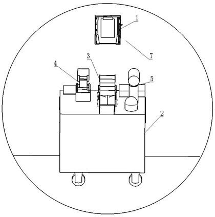
An intelligent ward data acquisition system based on the internet of things is shown in fig. 1-20 and comprises an acquisition system and a control system matched with the acquisition system; as shown in fig. 1, the acquisition system includes a data storage device 1 provided in each ward, and further includes a data collection device; the data collection device comprises a mobile platform 2, and a file collection device 3 and a file placement device 4 which are matched with the data storage device 1 are arranged on the mobile platform 2; the mobile platform 2 is provided with a camera device 5; the moving platform 2 is also internally provided with a storage device 6 and further comprises a moving device, and the moving device is controlled by the control system to move.
The camera device 5 comprises a camera, the camera is connected with a sixth electric telescopic rod, the sixth electric telescopic rod is arranged vertically below the camera, the camera is arranged on the sixth electric telescopic rod in a rotating mode, and the camera can rotate in the horizontal direction around the electric telescopic rod.
As shown in fig. 2-4, the data storage device includes a clamping mechanism and further includes a document storage mechanism cooperating with the clamping mechanism; the clamping mechanism comprises a clamping platform 101 fixedly connected on the ward wall 7, and the cross section of the clamping platform 101 is in a right trapezoid shape; the height of the cross section of the clamping platform 101 is attached to the wall 7, and the upper bottom of the cross section of the clamping platform 101 is shorter than the lower bottom; the clamping platform 101 comprises an inclined clamping surface 102, the top end of the clamping surface 102 being closer to the wall 7 than the bottom end of the clamping surface 102; a clamp holder parallel to the clamping surface 102 is arranged on the clamping platform 101; the clamp comprises a pair of symmetrical first clamping plates 103 arranged on a clamping surface 102, each first clamping plate 103 is perpendicular to the clamping surface 102, and each first clamping plate 103 is connected with the clamping surface 102 in a sliding manner; the length direction of each first clamping plate 103 is consistent with the length direction of the clamping surface 102, and the length direction of the clamping surface 102 is the direction of the oblique edge of the cross section of the clamping platform 101; the left end and the right end of the clamping surface 102 are fixedly connected with a first supporting plate 104 parallel to the first clamping plate 103, and the pair of first clamping plates 103 is arranged between the pair of first supporting plates 104; a plurality of compressed springs 105 are arranged between the first supporting plate 104 and the first clamping plate 103, and each compressed spring 105 is parallel to the clamping surface 102; a cleat opening mechanism is also connected to the pair of first cleats 103.
As shown in fig. 5-7, the clamping plate opening mechanism includes a first sliding groove 106 formed in the clamping platform 101, and a length direction of the first sliding groove 106 is perpendicular to a length direction of the first clamping plate 103; a pair of symmetrical first sliding plates 107 is arranged in the first sliding chute 106, and each first sliding plate 107 is fixedly connected with the first clamping plate 103; a pair of fourth sliding grooves 108 communicated with the first sliding grooves 106 are formed in the left side and the right side of the clamping surface 102, a connecting block 109 is arranged in each fourth sliding groove 108, and two ends of each connecting block 109 are fixedly connected with the first sliding plate 107 and the first clamping plate 103 respectively; one end of each first sliding plate 107 adjacent to the other first sliding plate 107 is provided with an inclined sliding connection surface 110, and each sliding connection surface 110 is perpendicular to the clamping surface 102; a wedge block 111 is further arranged in the first sliding chute 106, the wedge block 111 is arranged between the two sliding connection surfaces 110 and is in sliding connection with the sliding connection surfaces 110, the cross section of the wedge block 111 is an isosceles trapezoid with the top end longer than the bottom end, the two first sliding plates 107 are symmetrically arranged, and two surfaces parallel to the sliding connection surfaces 110 are arranged on the left side and the right side of the wedge block 111; a second chute 112 perpendicular to the first chute 106 is further formed in the first chute 106, and a first limit slider 113 fixedly connected with the wedge block 111 is arranged in the second chute 112; a first connecting rod 114 is hinged on the wedge-shaped block 111, the bottom end of the first connecting rod 114 is hinged with the wedge-shaped block 111, and the top end is hinged with a long rod-shaped labor-saving handle 115; a first cavity 116 communicated with the first chute 106 is formed in the clamping platform 101, the labor-saving handle 115 is arranged in the first cavity 116, and the first cavity 116 is communicated with the right side wall of the clamping platform 101; the first cavity 116 is parallel to the first sliding chute 106 and is arranged above the first sliding chute 106, a communicating groove 123 perpendicular to the first cavity 116 and the first sliding chute 106 is formed between the first cavity 116 and the first sliding chute 106, the communicating groove 123 communicates the first cavity 116 with the first sliding chute 106, and the first connecting rod 114 is arranged in the communicating groove 123; one end of the labor-saving handle 115 is hinged with a first fixed shaft 117, the first fixed shaft 117 is perpendicular to the labor-saving handle 115, and the first fixed shaft 117 is fixedly connected with the clamping platform 101; the other end of the labor-saving handle 115 is arranged outside the clamping platform 101. The labor-saving handle 115, the first connecting rod 114, the wedge block 111, the first sliding slot 106 and the first sliding plate 107 are all parallel to the clamping surface 102.
As shown in fig. 8, the document storage mechanism includes a third support plate 118 disposed between a pair of first clamp plates 103; an electric clamp is arranged at the top of the third supporting plate 118 and comprises a second clamping plate 119 parallel to the third supporting plate 118, and a first electric telescopic rod 120 is connected to the second clamping plate 119; the first electric telescopic rod 120 is fixedly connected to the third support plate 118, the first electric telescopic rod 120 and the third support plate 118 form an acute angle, and the extension direction of the first electric telescopic rod 120 extends obliquely upwards; the bottom end of the third supporting plate 118 is provided with a switch 121 connected with the first electric telescopic rod 120, and the switch 121 is a non-self-locking switch 121; the top of the clamping platform 101 is provided with a first groove 122, and the first groove 122 communicates the top of the clamping platform 101 with the third supporting plate 118.
As shown in fig. 9-10, the document collecting device 3 includes a first pressing block 301 matched with the switch 121, the first pressing block 301 is disposed below the switch 121, a vertical second electric telescopic rod 302 is connected below the first pressing block 301, and the bottom end of the second electric telescopic rod 302 is fixedly connected with the moving platform 2; the first pressing block 301 is also connected with a lifting ladder, and one end of the lifting ladder, which is far away from the first pressing block 301, is provided with a collecting box 303; the elevator comprises a head end inclined plate 304, a tail end inclined plate 305 and two middle inclined plates 306 arranged between the head end inclined plate 304 and the tail end inclined plate 305, wherein the head end inclined plate 304, the tail end inclined plate 305 and the middle inclined plates 306 are parallel to each other and are obliquely arranged; the top end of the head end sloping plate 304 is fixedly connected with the first pressing block 301, the head end sloping plate 304 comprises a sliding block 307 fixedly connected at the bottom of the head end sloping plate, and the sliding block 307 is arranged at the left side and the right side of the head end sloping plate 304; each middle inclined plate 306 comprises a sliding rail 308 which is in sliding connection with a sliding block 307, the sliding rails 308 are vertically arranged on two sides of the middle inclined plate 306, the sliding rails 308 are fixedly connected to the top end of the middle inclined plate 306, each middle inclined plate 306 comprises a sliding block 307 fixedly connected to the bottom of the middle inclined plate 306, and the sliding blocks 307 are arranged on the left side and the right side of the middle inclined plate 306; the structure of the tail-end sloping plate 305 is the same as that of the middle sloping plate 306, the top of the tail-end sloping plate 305 is fixedly connected with a slide rail 308, the bottom of the tail-end sloping plate 305 is fixedly connected with a slide block 307, and the collection box 303 is fixedly connected with a slide rail 308 connected with the slide block 307 on the tail-end sloping plate 305.
As shown in fig. 11-13, the collecting box 303 is a square structure with an open top end, the top end of the collecting box 303 is hinged with a pair of symmetrical door panels 309, and an automatic closing mechanism is arranged between each door panel 309 and the collecting box 303; the automatic closing mechanism comprises a second groove 310 formed in the top end of the collecting box 303, a second spring 311 is arranged in the second groove 310, the bottom end of the second spring 311 is fixedly connected with the bottom end of the second groove 310, and the top end of the second spring 311 is fixedly connected with the door panel 309; each door panel 309 is connected with a synchronous opening mechanism; the synchronous opening mechanism comprises a first connecting rope 312, one end of which is fixedly connected with the door panel 309, and the other end of the first connecting rope 312 is fixedly connected with a sliding block 307 on the tail end sloping plate 305; the synchronous opening mechanism further comprises a pulley block which is connected with the first connecting rope 312 in a sliding mode, the pulley block comprises a first fixed pulley 313 arranged on one side of the door panel 309, and the first fixed pulley 313 is arranged above the collecting box 303; the pulley block further comprises a second fixed pulley 314 connected to the collecting box 303, and the height position of the second fixed pulley 314 is located at the bottom of the sliding rail 308 on the collecting box 303; the pulley block further comprises a diverting pulley 315 arranged between the first fixed pulley 313 and the second fixed pulley 314; the shafts of the first fixed pulley 313, the second fixed pulley 314 and the diverting pulley 315 are all fixedly connected to the walls of the collecting box 303 on the left and right sides.
As shown in fig. 14 to 16, a paper feeding mechanism is further provided in the collection cassette 303, and the paper feeding mechanism includes a second support plate 316 disposed horizontally; the second support plate 316 is fixedly connected to the wall of the collecting box 303 adjacent to the elevator, horizontal second grooves 317 are arranged on the left side and the right side of the second support plate 316, the second grooves 317 are formed in the wall of the left side and the right side of the collecting box 303, and the second grooves 317 are arranged above the second support plate 316; each second groove 317 is connected with a conveyor, each conveyor comprises a second sliding plate 318 arranged in the second groove 317, each second sliding plate 318 is connected with a horizontal third electric telescopic rod 319, and the length direction of each third electric telescopic rod 319 is consistent with that of the second groove 317; the second sliding plate 318 is connected with a first rotating shaft 320 and a second rotating shaft 321, and the first rotating shaft 320 is connected with a fourth motor 322; a second driving gear 323 is connected to a shaft of the fourth motor 322, and a second driven gear 324 engaged with the second driving gear 323 is fixedly connected to the first rotating shaft 320; the first rotating shaft 320 and the second rotating shaft 321 are sleeved with an annular belt 325, and the annular belt 325 is arranged above the second supporting plate 316 and is parallel to the second supporting plate 316; a soft extrusion layer 326 is provided on the outer circumferential surface of the endless belt 325.
As shown in fig. 17-20, the document placing device 4 includes a second pressing block 401 engaged with the switch 121, a vertical fourth electric telescopic rod 402 is connected below the second pressing block 401, and the bottom end of the fourth electric telescopic rod 402 is fixedly connected with the moving platform 2; the second pressing block 401 is connected with a paper placing mechanism, the paper placing mechanism comprises a first rotating shaft 403 hinged with the second pressing block 401, the first rotating shaft 320 is horizontally arranged, the length direction of the first rotating shaft 320 is the left-right direction, one end of the first rotating shaft 403 is connected with a first motor 404, and the first motor 404 is fixedly connected with the second pressing block 401; the outer peripheral surface of the first rotating shaft 403 is fixedly connected with a connecting plate 405, and the connecting plate 405 is connected with a paper picker; the document placing device 4 further includes a paper 8 storage box 406 fitted to the paper picker, the paper 8 storage box 406 is a square structure with an open top end, a vertical groove 407 is formed in a wall (a wall on the front side) of the paper 8 storage box 406 close to the first rotating shaft 403, the vertical groove 407 communicates the inside and the outside of the paper 8 storage box 406, and the vertical groove 407 is fitted to the connecting plate 405 and is disposed right below the connecting plate 405.
The paper picker comprises a pair of symmetrical paper picking plates 408 which are rotatably connected at two sides of a connecting plate 405, the paper picking plates 408 are in a long plate structure, the length direction of the paper picking plates 408 is consistent with the length direction of the paper 8 storage box 406, and the length direction of the paper 8 storage box 406 is the front-back direction; a horizontal second connecting rod 409 is fixedly connected between the pair of paper taking plates 408; the bottom end of each paper taking plate 408 is provided with a pressure sensor 410; the bottom end of each paper taking plate 408 is provided with an air suction port 411, an air suction channel 412 communicated with the air suction port 411 is arranged in each paper taking plate 408, the second rotating shaft 321 and the connecting plate 405, and the connecting plate 405 is fixedly connected with a suction fan 413 communicated with the air suction channel 412; one of the paper taking plates 408 is fixedly connected with a first driven gear 414, the first driven gear 414 is engaged and connected with a first driving gear 415, the first driving gear 415 is connected with a second motor 416, and the second motor 416 is fixedly connected with a connecting plate 405. A horizontal electric door 417 is provided at an upper portion of the paper 8 storage cassette 406.
The control system comprises a control module, and the second electric telescopic rod 302, the third electric telescopic rod 319, the fourth electric telescopic rod 402, the first motor 404, the second motor 416, the pressure sensor 410, the electric door 417 and the camera device 5 are all connected with the control module; the control module is also connected with an alarm which is arranged on the mobile platform 2.
Example 2
The embodiment is an intelligent ward data acquisition system based on the internet of things, which adopts the following method and comprises the following steps,
step 1, monitoring ward instrument data. The control module controls the mobile platform 2 to patrol each ward according to a set route; when the mobile platform 2 moves into a ward, the control module controls the sixth electric telescopic lifting to adjust the height of the camera; the control module controls the camera to rotate, the angle of the camera is adjusted, and data, images and the like displayed by instruments in the ward are shot after the camera is adjusted; if the data of the instrument is abnormal (exceeds a set value), the control module controls the alarm to make a sound to remind medical personnel to cure the patient.
And 2, measuring and recording the patient data. When the medical staff checks the body temperature, the blood pressure and other physical signs of the patient, the labor-saving handle 115 of the data storage device 1 is pressed downwards; the labor-saving handle 115 rotates around the first fixed shaft 117 and drives the first connecting rod 114 and the wedge-shaped block 111 to move downwards, the inclined surface on the wedge-shaped block 111 moves downwards and extrudes the sliding connecting surface 110 of the first sliding plate 107, the two first sliding plates 107 move backwards and drive the two first clamping plates 103 to move backwards, and the compressed spring 105 is compressed; the third supporting plate 118 is taken down, the labor-saving handle 115 is loosened, the measured physical sign data of the patient is filled in the paper 8 of the third supporting plate 118, and after the data is filled, the labor-saving handle 115 is pressed down, and the third supporting plate 118 is put back. For the first use, the paper 8 is manually placed on the third support plate 118, and the paper is held by the electric clamp.
And 3, storing the patient data. After medical care personnel record physical sign data of patients every day (set time), the control module controls the mobile platform 2 to move to the front of a data storage device in a ward according to a set route; the control module controls the camera device 5 to adjust the position of the camera, takes a picture of the paper 8 on the third supporting plate 118 and uploads the picture to the database; after the picture is taken, the control module controls the mobile platform 2 to move, and the file collecting device 3 moves to the middle position below the data storage device 1; the control module controls the second electric telescopic rod 302 to ascend, and the second electric telescopic rod 302 drives the pressing block and the head end inclined plate 304 to ascend; when the slide block 307 of the head end sloping plate 304 moves to the top of the slide rail 308 of the middle sloping plate 306, the middle sloping plate 306 drives the middle sloping plate 306 to ascend, and finally the middle sloping plate 306 drives the tail end sloping plate 305 to ascend to the top end of the collection box 303; after the trailing-end sloping plate 305 rises, the slider 307 of the trailing-end sloping plate 305 drives the first connecting rope 312 to rise with the connected end thereof, the distance between the end of the first connecting rope 312 connected with the door panel 309 and the first fixed pulley 313 is shortened, the first connecting rope 312 drives the door panel 309 to open, and the second spring 311 extends. After the press block touches the switch 121, the first electric telescopic rod 120 extends, the second clamping plate 119 moves obliquely upwards, the electric clamp is opened, and the paper 8 falls into the head end inclined plate 304, and slides into the collection box 303 through the middle inclined plate 306 and the tail end inclined plate 305; the control module controls the third electric telescopic rod 319 to extend, so that the conveyor moves to the second supporting plate 316, the extrusion layer 326 extrudes the paper 8 onto the second supporting plate 316, the fourth motor 322 rotates and drives the first rotating shaft 320 to rotate so as to drive the annular belt 325 and the extrusion layer 326 to rotate, and the extrusion layer 326 conveys the paper 8 backwards until the paper 8 completely falls into the bottom end of the collecting box 303. The control module controls the third electric telescopic rod 319 to reset, the second electric telescopic rod 302 descends to reset, and the electric clamp and the elevator automatically reset; the second spring 311 compresses and the door panel 309 closes under the tension of the second spring 311.
Step 4, recording paper 8 is added. After the paper 8 is collected, the control module controls the mobile platform 2 to move, and the file placing device 4 moves to the middle position below the data storage device 1; the control module controls the electric door 417 to open, controls the fourth electric telescopic rod 402 to descend, and controls the suction fan 413 to open when the pressure sensor senses that the pressure reaches a set value, and the paper taking plate 408 sucks up the paper 8 at the top end; the control module controls the fourth electric telescopic rod 402 to ascend, controls the electric door 417 to be closed, and drives the second pressing block 401 and the connecting plate 405 to ascend through the fourth electric telescopic rod 402; the second pressing block 401 touches the switch 121, the electric clamp is opened, the control module controls the second motor 416 to rotate 180 degrees, the second motor 416 drives the first driving gear 415 and the first driven gear 414 to rotate, and the first driven gear 414 drives the paper taking plate 408 and the paper 8 to turn 180 degrees; the control module controls the first motor 404 to rotate by a set angle, and the first motor 404 drives the first rotating shaft 403, the connecting plate 405, the paper taking plate 408 and the paper 8 to rotate, so that the paper 8 is parallel to the third supporting plate 118; the control module controls the second electric telescopic rod 302 to descend to a set position (descend for a short distance), the switch 121 and the electric clamp reset, and the second clamping plate 119 clamps the paper 8 on the third supporting plate 118; the control module controls the suction fan 413 to be turned off, controls the first motor 404 and the second motor 416 to reset, and controls the fourth electric telescopic rod 402 to descend and reset at the same time.
And 5, circulating the step 3 and the step 4, and collecting data of each ward.
Example 3
Compared with the embodiment 1, the collecting box 303 of the embodiment is further provided with an arranging mechanism, as shown in fig. 21, the arranging mechanism comprises a sliding plate 327 arranged at the bottom end of the collecting box 303, and the sliding plate 327 is vertically arranged; the bottom end, the left side surface and the right side surface of the sliding plate 327 are fixedly connected with second limiting sliding blocks, the bottom end, the left inner wall and the right inner wall of the collecting box 303 are provided with fifth sliding grooves 329, and the second limiting sliding blocks are arranged in the fifth sliding grooves 329 and are in sliding connection with the fifth sliding grooves 329; the length direction of the fifth chute 329 is consistent with the length direction of the collecting box 303, namely the front and back direction of the collecting box 303; the sliding plate 327 is disposed at the front portion of the collecting box 303, a fifth electric telescopic rod is connected to the sliding plate 327, the fifth electric telescopic rod is fixedly connected to the bottom end of the collecting box 303, and the length direction of the fifth electric telescopic rod is consistent with the length direction of the fifth sliding groove 329.
During working, compared with embodiment 2, in this embodiment, after the third electric telescopic rod 319 is reset in step 3, the control module controls the fifth electric telescopic rod to extend, the fifth electric telescopic rod drives the sliding plate 327 to move backward, and the sliding plate 327 pushes the paper 8 to arrange the paper 8 in order; and the control module controls the fifth electric telescopic rod to reset.
Example 4
Compared with the embodiment 3, the storage device 6 of the present embodiment includes a row of storage drawers 601 disposed in the moving platform 2, as shown in fig. 22-28, four storage slots are disposed in the moving platform 2, and one storage drawer 601 is slidably connected to each storage slot; each storage drawer 601 is horizontally arranged, and each storage drawer 601 is connected with the mobile platform 2 in a sliding manner; each storage drawer 601 is connected with a first locking mechanism and a second locking mechanism; the first locking mechanism comprises a plurality of first springs 602, and a first spring 602 is arranged between each storage drawer 601 and the mobile platform 2; each first spring 602 is horizontally arranged and has the same sliding direction as the storage drawer 601, the length direction of the storage drawer 601 has the same sliding direction as the storage drawer, and the storage drawer 601 slides along the front-back direction of the mobile platform 2; the first locking mechanism also includes a spool 606 retractor coupled to each of the storage drawers 601. A second cavity 632 is formed in the movable platform 2, and the first locking mechanism and the second locking mechanism are disposed in the second cavity 632.
As shown in fig. 24, the reel 606 retractor includes third pulleys 603 connected to the rear end of each storage drawer 601, each third pulley 603 is disposed at a middle position in the width direction of the storage drawer 601, and each third pulley 603 is disposed horizontally; a pair of symmetrical tensioning pulleys 604 is arranged on each of the two sides of each third pulley 603, and each tensioning pulley 604 and the third pulley 603 are located in the same horizontal plane; a second connecting rope 605 is connected to the third pulleys 603 and the tensioning wheel, and the second connecting rope 605 is horizontally arranged; one end of the second connecting rope 605 is connected with a reel 606, and the reel 606 is connected with a third motor 607 which is coaxial with the reel and is vertically arranged; the other end of the second connecting rope 605 is fixedly connected with the moving platform 2; the third motor 607 is connected with a coded lock 608, and both the third motor 607 and the coded lock 608 are connected with the control module.
As shown in fig. 25-27, the second locking mechanism includes a lock including a horizontal bar 609 attached to the trailing end of the storage drawer 601, the horizontal bar 609 having a length that is aligned with the width of the storage drawer 601; the locker further comprises a horizontal plate 610 arranged above the horizontal rod 609, the horizontal plate 610 is fixedly connected with a vertical plate 611, and the horizontal rod 609 is arranged between the vertical plate 611 and the storage drawer 601; a pair of symmetrical and vertically downward supporting rods 612 is fixedly connected to the left side and the right side of the horizontal plate 610, a horizontal third connecting rod 613 is fixedly connected to each supporting rod 612, a barrel-shaped elastic rod 614 is sleeved on each third connecting rod 613, each elastic rod 614 is horizontally arranged, and the length directions of the elastic rods 614 and the third connecting rods 613 are consistent with the length direction of the storage drawer 601; a tension spring 615 is arranged between each third connecting rod 613 and the elastic rod 614, and the length direction of each tension spring 615 is consistent with the length direction of the elastic rod 614; one end of each of the two elastic rods 614 far away from the third connecting rod 613 is fixedly connected with a horizontal second fixed shaft 616, the second fixed shaft 616 is arranged above the horizontal rod 609, the second fixed shaft 616 is perpendicular to the elastic rods 614, and the second fixed shaft 616 is hinged with a vertical locking plate 617; the horizontal rod 609 is disposed between the locking plate 617 and the vertical plate 611; the locking plate 617 is arranged below the horizontal plate 610, one side of the locking plate 617, which is close to the vertical plate 611, is provided with a stopper 618, and the stopper 618 is fixedly connected with the horizontal plate 610; the horizontal plates 610 are all connected with a lifter. The elastic rod 614 is fixedly connected with a first magnet 619, and a second magnet attracted with the first magnet 619 is arranged on the locking plate 617.
As shown in fig. 28, the lifter includes a lever set, one end of the lever set is fixedly connected to the horizontal plate 610, and the other end is connected to an elastic button 621; the lever group comprises a fourth connecting rod 622 fixedly connected with the top end of the horizontal plate 610, and the fourth connecting rod 622 is vertically arranged; a vertical limiting hole is formed in the moving platform 2, and the fourth connecting rod 622 is arranged in the limiting hole, so that the fourth connecting rod 622 keeps moving vertically; the top end of the fourth connecting rod 622 is hinged with a fifth connecting rod 623, the other end of the fifth connecting rod 623 is hinged with a first lever 624, a horizontal third fixing shaft 625 is rotatably connected to the middle position of the first lever 624, and the third fixing shaft 625 is vertical to the length direction of the first lever 624; the length direction of the first lever 624 is aligned with the width direction of the storage drawer 601; one end of the first lever 624, which is far away from the third connecting rod 613, is hinged with a sixth connecting rod 626, the other end of the sixth connecting rod 626 is hinged with a second lever 627, the length direction of the second lever 627 is consistent with the length direction of the storage drawer 601, and a horizontal fourth fixed shaft 628 is rotatably connected to the middle position of the second lever 627; the fourth fixing shaft 628 is perpendicular to the length direction of the second lever 627; one end of the second lever 627, which is far away from the first lever 624, is hinged with a seventh connecting rod 629, the other end of the seventh connecting rod 629 is hinged with a third lever 630, the length direction of the third lever 630 is consistent with that of the second lever 627, the middle position of the third lever 630 is rotatably connected with a fifth fixed shaft 631, and the fifth fixed shaft 631 is parallel to the fourth fixed shaft 628; an elastic button 621 is disposed at an end of the third lever 630 remote from the second lever 627. The third fixed shaft 625, the fourth fixed shaft 628 and the fifth fixed shaft 631 are all fixedly connected with the mobile platform 2; the second lever 627 is disposed above the first lever 624, the third lever 630 is disposed above the second lever 627, and the elastic button 621 is disposed above the third lever 630. The first lever 624 of the second locking mechanism attached to each storage drawer 601 is of a different length, and the length of the first lever 624 is set by the lateral distance (the distance in the width direction of the storage drawer 601) between the horizontal plate 610 of each second locking mechanism and its corresponding resilient button 621. The control system further comprises a calling device arranged in each ward.
Compared with the embodiment 3, when the embodiment works, when medical care personnel need to replace common articles in a ward, the medical care personnel starts the calling device, the calling device sends a signal to the control module, and the control module controls the mobile platform 2 to move into the ward; the medical staff presses the elastic button 621 corresponding to the needed article, the elastic button 621 moves downwards to drive the front end of the third lever 630 to move downwards and the rear end to move upwards, the third lever 630 drives the front end of the second lever 627 to move upwards and the rear end to move downwards through the seventh connecting rod 629, the second lever 627 drives the left end of the first lever 624 to move downwards and the right end to move upwards through the sixth connecting rod 626, and the first lever 624 drives the fourth connecting rod 622 and the horizontal plate 610 to move upwards through the fifth connecting rod 623; the horizontal plate 610 drives the supporting rod 612, the third connecting rod 613, the elastic rod 614, the second fixed shaft 616 and the locking plate 617 to ascend, after the bottom end of the locking plate 617 ascends to the upper side of the horizontal rod 609, the tension spring 615 compresses and drives the elastic rod 614, the second fixed shaft 616 and the locking plate 617 to move towards the supporting rod 612; when the elastic button 621 is released, the horizontal plate 610 moves downwards under the action of the gravity of the horizontal plate and drives the locking plate 617 to move downwards, the locking plate 617 moves downwards to the horizontal rod 609 and then stops, and the horizontal rod 609 is unlocked; the reel 606 is started by inputting a password through the password lock 608, the reel 606 rotates forwards to release the second connecting rope 605, and the unlocked storage drawer 601 pops out under the elastic action of the first spring 602; after the storage drawer 601 is opened for a period of time (set time), the control module controls the third motor 607 to drive the reel 606 to rotate reversely, the reel 606 pulls the second connecting rope 605, the storage drawer 601 retracts and closes, and the second spring 311 compresses; when the horizontal rod 609 moves to contact with the locking plate 617, the horizontal rod 609 continues to move forwards, and the locking plate 617 is driven to rotate above the horizontal rod 609; after the horizontal rod 609 continues to move to leave the locking plate 617, the locking plate 617 rotates to be in a vertical state under the action of gravity and the action of the first magnet 619 and the second magnet; the control module controls the third motor 607 to drive the reel 606 to rotate forwardly and reset, the second connecting rope 605 is loosened, and the storage drawer 601 drives the horizontal rod 609 to reset, so that the horizontal rod 609 is blocked by the locking plate 617, and the horizontal rod 609 is prevented from being continuously locked after the locking plate 617 rises and falls.
- 上一篇:一种医用注射器针头装配设备
- 下一篇:一种腔镜器械下收下送用运送装置