Medical syringe needle head assembling equipment
阅读说明:本技术 一种医用注射器针头装配设备 (Medical syringe needle head assembling equipment ) 是由 袁由军 蔡晓盛 陈芒芒 于 2021-07-01 设计创作,主要内容包括:本发明公开了一种医用注射器针头装配设备,包括分度盘,其上分布有若干工位,分度盘通过电机驱动旋转,所述分度盘上分布有载具,工位包括第一工位至第八工位,在第一工位,将预制部分配件的注射器针头的针头连接器输送至载具;在第二工位,将针管插装至针头连接器的内孔;在第三工位,对针头连接器和针管的连接处进行点胶处理;在第四工位,对胶水进行固化处理;在第五工位,对针管进行校直处理;在第六工位,对装配完成的注射器针头进行监测;在第七工位,将不合格的注射器针头进行夹持并输送至废料箱;在第八工位,将合格的注射器针头进行夹持并输送至成品箱;本发明自动化程度高,具有装配、点胶、烘干、监测及筛选等功能,具有市场前景。(The invention discloses a medical syringe needle assembling device which comprises an index plate, wherein a plurality of stations are distributed on the index plate, the index plate is driven to rotate by a motor, carriers are distributed on the index plate, the stations comprise a first station to an eighth station, and a needle connector of a syringe needle of a prefabricated part accessory is conveyed to the carriers at the first station; at a second station, inserting the needle tube into an inner hole of the needle head connector; at the third station, the joint of the needle connector and the needle tube is subjected to dispensing treatment; curing the glue at a fourth station; straightening the needle tube at a fifth station; monitoring the assembled syringe needle at a sixth station; clamping the unqualified syringe needle and conveying the unqualified syringe needle to a waste bin at a seventh station; at an eighth station, clamping the qualified syringe needles and conveying the syringe needles to a finished product box; the automatic glue dispensing device is high in automation degree, has the functions of assembling, glue dispensing, drying, monitoring, screening and the like, and has market prospect.)
1. A medical syringe needle rigging equipment which characterized in that: the device comprises an index plate, wherein a plurality of stations are distributed on the index plate, the index plate is driven to rotate by a motor, carriers are distributed on the index plate and comprise a supporting plate, two mounting grooves for placing needle connectors are formed in the top of the supporting plate, a first side vertical plate and a second side vertical plate are respectively arranged on two sides of the supporting plate, the first side vertical plate and the second side vertical plate are oppositely arranged and are connected through a sliding column penetrating through the supporting plate, two ends of the sliding column are arranged in a protruding mode out of the supporting plate, the first side vertical plate is located on the inner side of the supporting plate, a butting block is correspondingly arranged on one side, facing the mounting groove, of the first side vertical plate, a moving groove communicated with the mounting groove and used for the butting block to slide is formed in the supporting plate, and a compression spring is arranged on the second side vertical plate, facing the supporting plate; the work stations comprise a first work station to an eighth work station, and in the first work station, a needle connector of a syringe needle of the prefabricated part fitting is conveyed to the carrier; at a second station, inserting the needle tube into an inner hole of the needle head connector; at the third station, the joint of the needle connector and the needle tube is subjected to dispensing treatment; curing the glue at a fourth station; straightening the needle tube at a fifth station; monitoring the assembled syringe needle at a sixth station; clamping the unqualified syringe needle and conveying the unqualified syringe needle to a waste bin at a seventh station; and in the eighth station, clamping the qualified syringe needle and conveying the syringe needle to a finished product box.
2. The medical syringe needle assembling apparatus according to claim 1, wherein: the needle connector feeding device comprises a vibrating disc, a feeding seat, a first pushing cylinder and a second pushing cylinder, wherein the vibrating disc is provided with a needle connector conveying function, the output end of the vibrating disc is provided with the feeding seat, the feeding seat is provided with two discharging channels for the needle connector to output, and the first pushing cylinder is arranged behind the feeding seat and used for driving the needle connector to output along the discharging channels; a first feeding manipulator component is arranged on one side of the conveying seat and comprises a first sliding seat, a first sliding seat driving cylinder, a first feeding fixing support, a first rotating motor, a first clamping jaw mounting plate and a first clamping jaw driving cylinder, the first feeding fixed bracket is arranged on the first sliding seat in a sliding way, the first sliding seat drives the air cylinder to be arranged on the first sliding seat and drives the first feeding fixed bracket to move towards the direction of the index plate, the first rotating motor is arranged at the top of the first feeding fixed bracket, the output end of the first rotating motor is fixedly connected with a first clamping jaw mounting plate, the first clamping jaw driving cylinder is arranged on the first clamping jaw mounting plate and drives the clamping jaws to open and close, when the first clamping jaw clamps the needle connector, the first rotating motor drives the first clamping jaw mounting plate to rotate by 90 degrees and is inserted onto the carrier.
3. The medical injector needle assembly apparatus of claim 2, wherein: a second feeding rail is arranged above the second station, a conveying belt is arranged in the second feeding rail and driven by a motor, a plurality of second clamping blocks used for fixing the needle tubes are equidistantly distributed on the conveying belt, a second feeding hopper is arranged above the second feeding rail, a second material blocking plate is arranged at the bottom of the second feeding hopper, and a second material blocking cylinder used for driving the second material blocking plate to move is arranged on one side of the second material blocking plate, so that the needle tubes are output one by one and enter the second clamping blocks; a second feeding mechanical arm assembly and a second assembling mechanical arm assembly are arranged on one side, close to the dividing plate, of the second feeding track, the second feeding mechanical arm assembly comprises a second feeding sliding table, a second feeding conveying seat, a second feeding driving cylinder, a second feeding rotating motor, a second feeding mounting plate, a second feeding clamping jaw and a second feeding clamping jaw cylinder, the second feeding conveying seat is slidably mounted on the second feeding sliding table, the second feeding driving cylinder is mounted on the second feeding conveying seat and drives the second feeding conveying seat to reciprocate on the second feeding sliding table, the second feeding rotating motor is mounted on the second feeding conveying seat, the output end of the second feeding rotating motor is fixedly connected with the second feeding mounting plate, the second feeding clamping jaw cylinder is mounted on the second feeding mounting plate and drives the second feeding clamping jaw to open and close, and close after the second feeding clamping jaw clamps clamp the needle tube, the clamping jaw mounting plate is driven to rotate by 90 degrees through a second feeding rotating motor and is conveyed to the position of a second assembly manipulator assembly; second assembly manipulator subassembly includes second assembly support, second assembly slide, second assembly lift cylinder, second assembly rotating electrical machines, second assembly clamping jaw and second assembly clamping jaw actuating cylinder, second assembly slide slidable mounting is in second assembly support and drives its slip through the cylinder, second assembly lift cylinder installs in second assembly slide, second assembly clamping jaw actuating cylinder installs in second assembly lift cylinder and drives second assembly clamping jaw and open and shut, second assembly clamping jaw below is provided with places the boss, when the graduated disk is rotatory needle connector to second assembly manipulator subassembly, gets the needle connector on the clamp carrier and carries to placing on the boss, second assembly manipulator subassembly clamp gets the hole of needle connector with its assembly to needle connector on the second material loading manipulator subassembly.
4. The medical syringe needle assembling apparatus according to claim 3, wherein: and the glue dispensing device is arranged at a third station and comprises a third mounting bracket, a third moving arm, a third driven arm, a third driving cylinder and a third connecting shaft, the third driving cylinder is mounted on the third mounting bracket and drives the third moving arm to reciprocate along the vertical direction, notches are formed in two sides of the third moving arm, the third driven arms are respectively inserted into two sides of the third moving arm, the third connecting shaft is provided with two parts and is positioned between the two third driven arms, and each third connecting shaft is provided with 2 glue dispensing devices.
5. The medical syringe needle assembling apparatus according to claim 4, wherein: and a fourth drying support is arranged at a fourth station, a drying chamber is arranged on the fourth drying support, a fourth drying chamber driving cylinder for driving the drying chamber to reciprocate along the vertical direction is arranged on the fourth drying support, and an ultraviolet illuminating lamp is arranged on the inner wall of the drying chamber.
6. The medical injector needle assembly apparatus of claim 5, wherein: and a fifth straightening unit is arranged at a fifth station and used for correcting the needle head.
7. The medical syringe needle assembling apparatus according to claim 6, wherein: and a CCD industrial camera shooting mechanism is arranged at a sixth station so as to detect the front and back sides of the needle tube or the defects of the workpiece and transmit data to the controller, the CCD industrial camera shooting mechanism comprises a sixth camera shooting support, a camera and an LED light source are arranged on the sixth camera shooting support, and the LED light source is a V-shaped piece with an upward opening.
8. The medical injector needle assembly apparatus of claim 7, wherein: at the seventh station, there is a seventh robotic arm for removing the product that is off-specification as monitored at the sixth station to a waste bin.
9. The medical injector needle assembly apparatus of claim 8, wherein: at the eighth station, an eighth robotic arm is provided for removing the qualified products to the product bin.
Technical Field
The invention relates to the technical field of injector production equipment, in particular to medical injector needle assembling equipment.
Background
The syringe includes cylinder, piston rod and syringe needle, and the syringe needle includes syringe needle connector and needle tubing, and the syringe needle rigging equipment that urgently needs on the market now with a syringe needle, with the needle tubing cartridge in syringe needle connector hole, then need through some glue, dry, carry out multiple processes such as alignment processing, product monitoring to the needle tubing.
Disclosure of Invention
The invention aims to overcome the defects and shortcomings of the prior art and provide a medical syringe needle assembling device.
In order to achieve the purpose, the invention provides the following technical scheme: a medical injector needle head assembling device comprises an index plate, a plurality of stations are distributed on the index plate, the index plate is driven to rotate by a motor, a carrier is distributed on the index plate and comprises a supporting plate, the top of the supporting plate is provided with two mounting grooves for placing the needle connectors, the two sides of the supporting plate are respectively provided with a first side vertical plate and a second side vertical plate, the first side vertical plate and the second side vertical plate are oppositely arranged and are connected through a sliding column penetrating through the support plate, two ends of the sliding column are arranged to protrude out of the support plate, the first side vertical plate is positioned at the inner side of the supporting plate, and one side of the first side vertical plate facing the mounting groove is correspondingly provided with a butting block, the supporting plate is provided with a moving groove communicated with the mounting groove for the abutting block to slide, the second side vertical plate is positioned outside the supporting plate, and a compression spring is arranged on one side of the second side vertical plate facing the supporting plate; the work stations comprise a first work station to an eighth work station, and in the first work station, a needle connector of a syringe needle of the prefabricated part fitting is conveyed to the carrier; at a second station, inserting the needle tube into an inner hole of the needle head connector; at the third station, the joint of the needle connector and the needle tube is subjected to dispensing treatment; curing the glue at a fourth station; straightening the needle tube at a fifth station; monitoring the assembled syringe needle at a sixth station; clamping the unqualified syringe needle and conveying the unqualified syringe needle to a waste bin at a seventh station; and in the eighth station, clamping the qualified syringe needle and conveying the syringe needle to a finished product box.
As a preferred technical scheme of the invention, a vibration disc for conveying the needle connectors is arranged at a first station, a conveying seat is arranged at the output end of the vibration disc, two discharging channels for the needle connectors to output are arranged on the conveying seat, and a first material pushing cylinder for driving the needle connectors to output along the discharging channels is arranged behind the conveying seat; a first feeding manipulator component is arranged on one side of the conveying seat and comprises a first sliding seat, a first sliding seat driving cylinder, a first feeding fixing support, a first rotating motor, a first clamping jaw mounting plate and a first clamping jaw driving cylinder, the first feeding fixed bracket is arranged on the first sliding seat in a sliding way, the first sliding seat drives the air cylinder to be arranged on the first sliding seat and drives the first feeding fixed bracket to move towards the direction of the index plate, the first rotating motor is arranged at the top of the first feeding fixed bracket, the output end of the first rotating motor is fixedly connected with a first clamping jaw mounting plate, the first clamping jaw driving cylinder is arranged on the first clamping jaw mounting plate and drives the clamping jaws to open and close, when the first clamping jaw clamps the needle connector, the first rotating motor drives the first clamping jaw mounting plate to rotate by 90 degrees and is inserted onto the carrier.
As a preferred technical scheme of the invention, a second feeding track is arranged above a second station, a conveying belt is arranged in the second feeding track, the conveying belt is driven by a motor, a plurality of second clamping blocks for fixing needle tubes are equidistantly distributed on the conveying belt, a second feeding funnel is arranged above the second feeding track, a second material blocking plate is arranged at the bottom of the second feeding funnel, and a second material blocking cylinder for driving the second material blocking plate to move is arranged on one side of the second material blocking plate, so that the needle tubes are output one by one and enter the second clamping blocks; a second feeding mechanical arm assembly and a second assembling mechanical arm assembly are arranged on one side, close to the dividing plate, of the second feeding track, the second feeding mechanical arm assembly comprises a second feeding sliding table, a second feeding conveying seat, a second feeding driving cylinder, a second feeding rotating motor, a second feeding mounting plate, a second feeding clamping jaw and a second feeding clamping jaw cylinder, the second feeding conveying seat is slidably mounted on the second feeding sliding table, the second feeding driving cylinder is mounted on the second feeding conveying seat and drives the second feeding conveying seat to reciprocate on the second feeding sliding table, the second feeding rotating motor is mounted on the second feeding conveying seat, the output end of the second feeding rotating motor is fixedly connected with the second feeding mounting plate, the second feeding clamping jaw cylinder is mounted on the second feeding mounting plate and drives the second feeding clamping jaw to open and close, and close after the second feeding clamping jaw clamps clamp the needle tube, the clamping jaw mounting plate is driven to rotate by 90 degrees through a second feeding rotating motor and is conveyed to the position of a second assembly manipulator assembly; second assembly manipulator subassembly includes second assembly support, second assembly slide, second assembly lift cylinder, second assembly rotating electrical machines, second assembly clamping jaw and second assembly clamping jaw actuating cylinder, second assembly slide slidable mounting is in second assembly support and drives its slip through the cylinder, second assembly lift cylinder installs in second assembly slide, second assembly clamping jaw actuating cylinder installs in second assembly lift cylinder and drives second assembly clamping jaw and open and shut, second assembly clamping jaw below is provided with places the boss, when the graduated disk is rotatory needle connector to second assembly manipulator subassembly, gets the needle connector on the clamp carrier and carries to placing on the boss, second assembly manipulator subassembly clamp gets the hole of needle connector with its assembly to needle connector on the second material loading manipulator subassembly.
As a preferred technical scheme of the present invention, a dispensing device is provided at a third station, and the dispensing device includes a third mounting bracket, a third moving arm, a third driven arm, a third driving cylinder, and a third connecting shaft, the third driving cylinder is mounted on the third mounting bracket and drives the third moving arm to reciprocate along a vertical direction, notches are provided at two sides of the third moving arm, the third driven arm is respectively inserted into two sides of the third moving arm, the third connecting shaft is provided with two parts and is located between the two third driven arms, and each third connecting shaft is provided with 2 dispensing devices.
As a preferable technical scheme of the invention, a fourth drying bracket is arranged at a fourth station, a drying chamber is arranged on the fourth drying bracket, a fourth drying chamber driving cylinder for driving the drying chamber to reciprocate along the vertical direction is arranged on the fourth drying bracket, and an ultraviolet illuminating lamp is arranged on the inner wall of the drying chamber.
As a preferred technical scheme of the invention, a fifth straightening unit is arranged at a fifth station and is used for correcting the needle head.
As a preferred technical scheme of the present invention, a CCD industrial camera mechanism is provided at a sixth station to detect the front and back sides of the needle tube or the defects of the workpiece and transmit data to the controller, the CCD industrial camera mechanism includes a sixth camera bracket, the sixth camera bracket is provided with a camera and an LED light source, and the LED light source is a V-shaped member with an upward opening.
As a preferred technical scheme of the invention, a seventh mechanical arm is arranged at the seventh station and is used for taking down the products which are unqualified in the monitoring result at the sixth station to a waste bin.
As a preferred technical solution of the present invention, at the eighth station, an eighth robot arm is provided for taking down the qualified products to the finished product bin.
The invention has the following beneficial effects: dividing work by arranging 8 stations, and conveying a needle connector of a syringe needle of a prefabricated part accessory to a carrier at a first station; at a second station, inserting the needle tube into an inner hole of the needle head connector; at the third station, the joint of the needle connector and the needle tube is subjected to dispensing treatment; curing the glue at a fourth station; straightening the needle tube at a fifth station; monitoring the assembled syringe needle at a sixth station; clamping the unqualified syringe needle and conveying the unqualified syringe needle to a waste bin at a seventh station; at an eighth station, clamping the qualified syringe needles and conveying the syringe needles to a finished product box; the automatic glue dispensing device is simple in structure, high in automation degree, free of manual operation in the whole process, capable of achieving the functions of assembling, glue dispensing, drying, monitoring, screening and the like, and high in market prospect.
Drawings
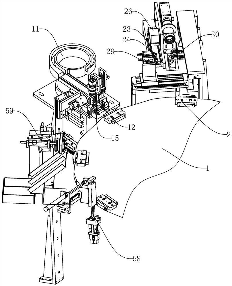
FIG. 1 is a schematic view of the left side structure of the complete machine of the present invention;
FIG. 2 is a schematic view of the right side of the complete machine of the present invention;
figure 3 is a perspective view of a first loading robot assembly of the present invention;
figure 4 is a perspective view of a second loading robot assembly and a second assembly robot assembly of the present invention;
FIG. 5 is a perspective view of the dispensing apparatus of the present invention;
FIG. 6 is a perspective view of the CCD industrial camera of the present invention;
FIG. 7 is an enlarged view of portion A of FIG. 4;
fig. 8 is a schematic view of a carrier structure according to the present invention.
Reference numerals: 1. an index plate; 2. a carrier; 3. a support plate; 4. mounting grooves; 5. a first side vertical plate; 6. a second side vertical plate; 7. a sliding post; 8. a butting block; 9. a moving groove; 10. a compression spring; 11. a vibrating pan; 12. a conveying seat; 13. a discharge channel; 14. a first material pushing cylinder; 15. a first feeding manipulator assembly; 16. a first sliding seat; 17. the first sliding seat drives the cylinder; 18. a first feeding fixing support; 19. a first rotating electrical machine; 20. a first jaw; 21. a first jaw mounting plate; 22. the first clamping jaw drives the cylinder; 23. a second feed track; 24. a conveyor belt; 25. a second clamp block; 26. a second feed hopper; 27. a second retainer plate; 28. a second material blocking cylinder; 29. a second feeding manipulator assembly; 30. a second feeding sliding table; 31. a second feeding conveying seat; 32. a second feeding driving cylinder; 33. a second feeding rotating motor; 34. a second feeding mounting plate; 35. a second feeding jaw; 36. a second feeding clamping jaw cylinder; 37. a second assembly robot assembly; 38. a second mounting bracket; 39. a second assembly slide; 40. a second assembly lifting cylinder; 41. a second assembled rotating electrical machine; 42. a second assembly jaw; 43. a second assembly clamping jaw driving cylinder; 44. a dispensing device; 45. a third mounting bracket; 46. a third moving arm; 47. a third driven arm; 48. a third driving cylinder; 49. a third connecting shaft; 50. a glue dispenser; 51. a fourth drying support; 52. a drying chamber; 53. the fourth drying chamber drives a cylinder; 54. a fifth straightening unit; 55. a CCD industrial camera shooting mechanism; 56. a sixth camera shooting bracket; 57. an LED light source; 58. a seventh mechanical arm; 59. an eighth mechanical arm; 60. a camera; 61. and placing the boss.
Detailed Description
In order to make the technical means, the original characteristics, the achieved purposes and the effects of the invention easily understood, the invention is further described below with reference to the specific embodiments and the attached drawings, but the following embodiments are only the preferred embodiments of the invention, and not all embodiments. Based on the embodiments in the implementation, other embodiments obtained by those skilled in the art without any creative efforts belong to the protection scope of the present invention.
Specific embodiments of the present invention are described below with reference to the accompanying drawings.
As shown in fig. 1 to 8, a medical injector needle head assembling apparatus includes an index plate 1, on which a plurality of stations are distributed, the index plate 1 is driven by a motor to rotate, carriers 2 are distributed on the index plate 1, each carrier 2 includes a supporting plate 3, two mounting grooves 4 for placing needle head connectors are arranged at the top of the supporting plate 3, a first side vertical plate 5 and a second side vertical plate 6 are respectively arranged at two sides of the supporting plate 3, the first side vertical plate 5 and the second side vertical plate 6 are oppositely arranged and connected with each other through a sliding column 7 penetrating the supporting plate 3, two ends of the sliding column 7 protrude out of the supporting plate 3, the first side vertical plate 5 is located at the inner side of the supporting plate 3, and the first side vertical plate 5 is correspondingly provided with a butt-joint block 8 towards one side of the mounting groove 4, a moving groove 9 communicated with the mounting groove 4 for sliding the butt-joint block 8 is arranged on the supporting plate 3, the second side vertical plate 6 is located at the outer side of the supporting plate 3 and the second side vertical plate 6 is arranged towards one side of the supporting plate 3 A compression spring 10; the stations comprise a first station to an eighth station, and in the first station, a needle connector of a syringe needle of the prefabricated part fitting is conveyed to the carrier 2; at a second station, inserting the needle tube into an inner hole of the needle head connector; at the third station, the joint of the needle connector and the needle tube is subjected to dispensing treatment; curing the glue at a fourth station; straightening the needle tube at a fifth station; monitoring the assembled syringe needle at a sixth station; clamping the unqualified syringe needle and conveying the unqualified syringe needle to a waste bin at a seventh station; and in the eighth station, clamping the qualified syringe needle and conveying the syringe needle to a finished product box.
At a first station, a vibration disc 11 for conveying a needle connector is arranged, a conveying seat 12 is arranged at the output end of the vibration disc 11, two discharging channels 13 for outputting the needle connector are formed in the conveying seat 12, and a first material pushing cylinder 14 for driving the needle connector to output along the discharging channels 13 is arranged behind the conveying seat 12; a first feeding manipulator assembly 15 is arranged on one side of the conveying seat 12, the first feeding manipulator assembly 15 comprises a first sliding seat 16, a first sliding seat driving cylinder 17, a first feeding fixing support 18, a first rotating motor 19, a first clamping jaw 20, a first clamping jaw mounting plate 21 and a first clamping jaw driving cylinder 22, the first feeding fixing support 18 is slidably mounted on the first sliding seat 16, the first sliding seat driving cylinder 17 is mounted on the first sliding seat 16 and drives the first feeding fixing support 18 to move towards the direction of the dividing plate 1, the first rotating motor 19 is mounted on the top of the first feeding fixing support 18, the output end of the first rotating motor 19 is fixedly connected with the first clamping jaw mounting plate 21, the first clamping jaw driving cylinder 22 is mounted on the first clamping jaw mounting plate 21 and drives the first clamping jaw 20 to open and close, and after the first clamping jaw 20 clamps the needle connector, the first rotating motor 19 drives the first chuck mounting plate 21 to rotate 90 ° and is inserted onto the carrier 2 of the index plate 1.
A second feeding rail 23 is arranged above the second station, a conveyor belt 24 is arranged in the second feeding rail 23, the conveyor belt 24 is driven by a motor, a plurality of second clamping blocks 25 used for fixing needle tubes are equidistantly distributed on the conveyor belt 24, a second feeding hopper 26 is arranged above the second feeding rail 23, a second material blocking plate 27 is arranged at the bottom of the second feeding hopper 26, and a second material blocking cylinder 28 used for driving the second material blocking plate 27 to move is arranged on one side of the second material blocking plate 27, so that the needle tubes are output one by one and enter the second clamping blocks 25; a second feeding manipulator assembly 29 and a second assembling manipulator assembly 37 are arranged on one side, close to the dividing plate 1, of the second feeding track 23, the second feeding manipulator assembly 29 comprises a second feeding sliding table 30, a second feeding conveying seat 31, a second feeding driving cylinder 32, a second feeding rotating motor 33, a second feeding mounting plate 34, a second feeding clamping jaw 35 and a second feeding clamping jaw cylinder 36, the second feeding conveying seat 31 is slidably mounted on the second feeding sliding table 30, the second feeding driving cylinder 32 is mounted on the second feeding conveying seat 31 and drives the second feeding conveying seat 31 to reciprocate on the second feeding sliding table 30, the second feeding rotating motor 33 is mounted on the second feeding conveying seat 31, the second feeding mounting plate 34 is fixedly connected with the output end of the second feeding rotating motor 33, the second feeding clamping jaw 35 cylinder is mounted at the bottom of the second feeding mounting plate 34 and drives the second feeding clamping jaw 35 to open and close, after the needle tube is clamped by the second feeding clamping jaw 35, the clamping jaw mounting plate is driven by the second feeding rotating motor 33 to rotate for 90 degrees and is conveyed to the position of a second assembling manipulator assembly 37; the second assembling manipulator assembly 37 comprises a second assembling bracket 38, a second assembling slide 39, a second assembling lifting cylinder 40, a second assembling rotating motor 41, a second assembling clamping jaw 42 and a second assembling clamping jaw driving cylinder 43, the second mounting slide 39 is slidably mounted on the second mounting bracket 38 and is driven to slide by means of an air cylinder, the second assembling lifting cylinder 40 is arranged on the second assembling sliding seat 39, the second assembling clamping jaw driving cylinder 43 is arranged on the second assembling lifting cylinder 40 and drives the second assembling clamping jaw 42 to open and close, a placing boss 61 is arranged below the second assembling clamping jaw 42, when the index plate 1 rotates the needle connectors to the second assembling manipulator assembly 37, the needle connectors on the gripping carrier 2 are conveyed to the placing boss 61, the second assembling manipulator assembly 37 picks up the needle tube on the second feeding manipulator assembly 29 and assembles the needle tube into the inner hole of the needle connector.
And at the third station, a glue dispensing device 44 is provided, the glue dispensing device 44 includes a third mounting bracket 45, a third moving arm 46, a third driven arm 47, a third driving cylinder 48 and a third connecting shaft 49, the third driving cylinder 48 is mounted on the third mounting bracket 45 and drives the third moving arm 46 to reciprocate along the vertical direction, notches are provided at two sides of the third moving arm 46, the third driven arms 47 are respectively inserted at two sides of the third moving arm 46, the third connecting shaft 49 is provided with two parts and is located between the two third driven arms 47, and each third connecting shaft 49 is provided with 2 glue dispensers 50.
And a fourth station is provided with a fourth drying bracket 51, a drying chamber 52 is arranged on the fourth drying bracket 51, a fourth drying chamber driving air cylinder 53 for driving the drying chamber 52 to reciprocate along the vertical direction is arranged on the fourth drying bracket 51, and an ultraviolet illuminating lamp is arranged on the inner wall of the drying chamber 52.
At the fifth station, a fifth straightening unit 54 is provided for correcting the needle head to ensure the perpendicularity of the needle head.
And a CCD industrial camera mechanism 55 is arranged at the sixth station so as to detect whether the front and back sides of the needle tube are assembled wrongly or the workpiece is defective and transmit data to the controller, wherein the CCD industrial camera mechanism 55 comprises a sixth camera bracket 56, a camera 60 and an LED light source 57 are arranged on the sixth camera bracket 56, and the LED light source 57 is a V-shaped piece with an upward opening.
At the seventh station, there is a seventh robotic arm 58 for removing products that have been monitored at the sixth station to indicate a reject to the waste bin.
At the eighth station, there is an eighth robotic arm 59 for removing the good product to the finished bin.
The work division is carried out by arranging 8 stations, and in the first station, a needle connector of a syringe needle of a prefabricated part accessory is conveyed to the carrier 2; at a second station, inserting the needle tube into an inner hole of the needle head connector; at the third station, the joint of the needle connector and the needle tube is subjected to dispensing treatment; curing the glue at a fourth station; straightening the needle tube at a fifth station; monitoring the assembled syringe needle at a sixth station; clamping the unqualified syringe needle and conveying the unqualified syringe needle to a waste bin at a seventh station; at the eighth station, carry out the centre gripping with qualified syringe needle and carry to the finished product case, degree of automation is high, has functions such as assembly, point and glues, stoving, monitoring and screening, and market prospect is high.
In the present invention, unless otherwise expressly stated or limited, "above" or "below" a first feature means that the first and second features are in direct contact, or that the first and second features are not in direct contact but are in contact with each other via another feature therebetween. Also, the first feature being "on," "above" and "over" the second feature includes the first feature being directly on and obliquely above the second feature, or merely indicating that the first feature is at a higher level than the second feature. A first feature being "under," "below," and "beneath" a second feature includes the first feature being directly under and obliquely below the second feature, or simply meaning that the first feature is at a lesser elevation than the second feature.
The foregoing shows and describes the general principles, essential features, and advantages of the invention. It will be understood by those skilled in the art that the present invention is not limited to the embodiments described above, that the preferred embodiments of the present invention are described in the above embodiments and the description, and not intended to limit the present invention, and that various changes and modifications may be made within the scope of the invention as claimed, which is defined by the appended claims and their equivalents, without departing from the spirit and scope of the invention.
- 上一篇:没有了
- 下一篇:适于航空发动机单元体的多工位装配平台控制方法