Reciprocating extrusion type strip seedbed construction unit
阅读说明:本技术 往复运动挤压式条带种床构建单体 (Reciprocating extrusion type strip seedbed construction unit ) 是由 王奇 王金武 郭方宇 王金峰 周文琪 唐汉 孙小博 于 2021-08-23 设计创作,主要内容包括:往复运动挤压式条带种床构建单体属于农业机械;在连接架上相互对称且留有间距的安装吊挂臂,在吊挂臂上同时安装由端面凸轮A、锯齿圆盘犁刀、弹簧座A、链轮A、刀轴、顶杆A、压力弹簧A、平面推力轴承A构成的条带种床土壤、秸秆、根茬粉碎切割装置和由端面齿轮B、限深防滑压秸轮、弹簧座B、链轮B、轮轴、顶杆B、压力弹簧B、平面推力轴承B构成的作业辅助装置,链条套装在链轮A和链轮B上;本单体利用锯齿圆盘犁刀的旋转和轴向往复运动在完成对条带种床土壤、根茬切碎同时,又对条带种床土壤进行向内的对向挤压粉碎与归拢聚合,具有结构独特、合理、动力消耗少、构建的条带种床质量好、作业效率高的特点。(A reciprocating extrusion type strip seedbed construction monomer belongs to agricultural machinery; the device comprises a connecting frame, a plurality of hanging arms, a strip seedbed soil, straws and stubble smashing and cutting device and an operation auxiliary device, wherein the hanging arms are arranged on the connecting frame symmetrically and spaced, the hanging arms are simultaneously arranged on the hanging arms, the strip seedbed soil, the straws and the stubble smashing and cutting device comprises an end face cam A, a sawtooth disc coulter, a spring seat A, a chain wheel A, a cutter shaft, a top rod A, a pressure spring A and a plane thrust bearing A, the operation auxiliary device comprises an end face gear B, a depth-limiting anti-sliding straw pressing wheel, a spring seat B, a chain wheel B, a wheel shaft, a top rod B, a pressure spring B and a plane thrust bearing B, and a chain is sleeved on the chain wheel A and the chain wheel B; the single body utilizes the rotation and axial reciprocating motion of the saw-tooth disc coulter to cut up the strip seedbed soil and root stubbles, and simultaneously carries out inward opposite extrusion crushing and gathering polymerization on the strip seedbed soil, and has the characteristics of unique and reasonable structure, low power consumption, good quality of the constructed strip seedbed and high operation efficiency.)
1. A reciprocating extrusion type strip seedbed construction unit is characterized in that: hanging arms (2) are symmetrically arranged on the connecting frame (1) at intervals, and end cams A (3) and end cams B (8) are fixedly arranged on the hanging arms (2) with axes parallel to each other; a self-lubricating shaft sleeve A (13) is fixedly installed in a central hole of the end face cam A (3), a cutter shaft (11) with a push rod A (12) is radially positioned, circumferentially rotatable and axially movably inserted and installed in a sleeve hole of the self-lubricating shaft sleeve A (13), the push rod A (12) is in contact fit with the end face cam A (3), a spring seat A (5) is fixedly installed on the cutter shaft (11) and positioned at the outer side of the self-lubricating shaft sleeve A (13) through a plane thrust bearing A (15), a pressure spring A (14) is sleeved on the cutter shaft (11) and positioned in the spring seat A (5), the inner end face and the outer end face of the pressure spring A (14) are respectively in contact fit with the end face cam A (3) and the plane thrust bearing A (15), a chain wheel A (6) is fixedly installed at the outer end part of the cutter shaft (11), and the chain wheel A (6) is fixedly installed with the spring seat A (5), a saw-tooth disc coulter (4) is fixedly arranged at the inner end part of the cutter shaft (11); a self-lubricating shaft sleeve B (18) is fixedly installed in a central hole of the end face cam B (8), a wheel shaft (16) with a push rod B (17) is radially positioned, circumferentially rotatable and axially movably inserted and installed in a sleeve hole of the self-lubricating shaft sleeve B (18), the push rod B (17) is in contact fit with the end face cam B (8), a spring seat B (9) is fixedly installed on the wheel shaft (16) and positioned at the outer side of the self-lubricating shaft sleeve B (18) through a plane thrust bearing B (20), a pressure spring B (19) is sleeved on the wheel shaft (16) and positioned in the spring seat B (9), the inner end face and the outer end face of the pressure spring B (19) are respectively in contact fit with the end face cam B (8) and the plane thrust bearing B (20), a chain wheel B (10) is fixedly installed at the outer end part of the wheel shaft (16), and the chain wheel B (10) is fixedly installed with the spring seat B (9), a depth-limiting anti-skid straw pressing wheel (7) is fixedly arranged at the inner end part of the wheel shaft (16); the chain (21) is sleeved on the chain wheel A (6) and the chain wheel B (10); the lowest point of the depth-limiting anti-skid straw pressing wheel (7) is higher than the lowest point of the sawtooth disc coulter (4).
Technical Field
The invention belongs to agricultural machinery, and mainly relates to an operation unit suitable for constructing a farming mode by using a strip seedbed.
Background
The construction of the strip seedbed is a strip seedbed cultivation mode which reasonably loosens soil and straw stubbles in a cultivation layer on uncultivated land to obtain a strip seedbed suitable for the sowing operation of a sowing machine, and the operation parts of the strip seedbed construction mode play an important role in the quality and the efficiency of the strip seedbed construction. At present, the conventional strip seedbed construction device mainly adopts an active rotating structure, and during operation, soil and straw stubbles at a seedbed part are cut and loosened by a rotary tillage cutter rotating at a high speed, so that the technical problems of high power consumption, serious mechanical vibration, much loss of the seedbed soil when being thrown out of a strip part and poor seedbed quality exist; in addition, the passive plough type strip seedbed construction device adopts a structure that two fixed and opposite disc coulters are installed, during operation, the two disc coulters passively rotate under the action of soil resistance, strip loosening operation is carried out on the soil at the inner side parts relative to the two disc coulters, and production and use practices find that the technical requirements of mechanical sowing on the strip seedbed cannot be met due to the fact that the structural device has obviously insufficient disturbance crushing capacity on seedbed soil and chopping capacity on root stubbles and straws, the strip seedbed is poor in quality and unstable in operation depth.
Disclosure of Invention
The invention aims to solve the problems in the prior art, and researches a reciprocating motion extrusion type strip seedbed construction monomer with a new structure by combining the actual requirements of construction and use of the strip seedbed at present, so as to achieve the purposes of good operation quality, high operation efficiency and provision of a good strip seedbed for mechanical precision seeding operation.
The invention aims to realize the aims that hanging arms are symmetrically arranged on a connecting frame at intervals, and an end cam A and an end cam B are fixedly arranged on the hanging arms with axes parallel to each other; a self-lubricating shaft sleeve A is fixedly installed in a central hole of the end face cam A, a cutter shaft with a push rod A is radially positioned, circumferentially rotatable and axially movably inserted and installed in a sleeve hole of the self-lubricating shaft sleeve A, the push rod A is in contact fit with the end face cam A, a spring seat A is fixedly installed on the cutter shaft and positioned at the outer side of the self-lubricating shaft sleeve A through a plane thrust bearing A, a pressure spring A is sleeved on the cutter shaft and positioned in the spring seat A, the inner end face and the outer end face of the pressure spring A are respectively in contact fit with the end face cam A and the plane thrust bearing A, a chain wheel A is fixedly installed on the outer end portion of the cutter shaft, the chain wheel A is fixedly installed with the spring seat A, and a sawtooth disc coulter is fixedly installed on the inner end portion of the cutter shaft; a self-lubricating shaft sleeve B is fixedly installed in a central hole of the end face cam B, a wheel shaft with a push rod B is radially positioned, circumferentially rotatable and axially movably inserted and installed in a sleeve hole of the self-lubricating shaft sleeve B, the push rod B is in contact fit with the end face cam B, a spring seat B is fixedly installed on the wheel shaft and positioned at the outer side of the self-lubricating shaft sleeve B through a plane thrust bearing B, a pressure spring B is sleeved on the wheel shaft and positioned in the spring seat B, the inner end face and the outer end face of the pressure spring B are respectively in contact fit with the end face cam B and the plane thrust bearing B, a chain wheel B is fixedly installed on the outer end part of the wheel shaft, the chain wheel B is fixedly installed with the spring seat B, and a depth-limiting anti-skidding straw pressing wheel is fixedly installed on the inner end part of the wheel shaft; the chain is sleeved on the chain wheel A and the chain wheel B; the lowest point of the depth-limiting anti-slip straw pressing wheel is higher than the lowest point of the saw-tooth disc coulter, so that the reciprocating extrusion type strip seedbed construction single body is formed.
The invention utilizes the rotation motion and the axial reciprocating motion of the sawtooth disc coulter to complete the cutting operation of the soil straws and stubbles on the strips, and simultaneously carries out inward opposite extrusion on the soil of the strip seed bed, thereby not only avoiding the loss of the soil of the strip seed bed, but also playing a good soil crushing effect.
Drawings
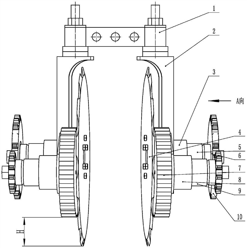
FIG. 1 is a schematic view of the overall structure of a reciprocating extrusion type strip seedbed building unit;
FIG. 2 is a partial view taken from the direction A of FIG. 1;
FIG. 3 is a folded sectional view taken along line B-B of FIG. 2;
fig. 4 is a partial sectional view taken along line C-C of fig. 3.
Description of part numbers in the figures:
1. the device comprises a connecting frame, 2, a hanging arm, 3, end face cams A and 4, a sawtooth disc coulter, 5, spring seats A and 6, chain wheels A and 7, a depth-limiting anti-skid straw pressing wheel 8, end face cams B and 9, spring seats B and 10, chain wheels B and 11, a cutter shaft 12, ejector rods A and 13, self-lubricating shaft sleeves A and 14, pressure springs A and 15, plane thrust bearings A and 16, a wheel shaft 17, ejector rods B and 18, self-lubricating shaft sleeves B and 19, pressure springs B and 20, plane thrust bearings B and 21 and a chain.
Detailed Description
The following detailed description of the inventive embodiments is provided in connection with the accompanying drawings. A reciprocating extrusion type strip seedbed constructing single body is characterized in that hanging arms 2 are symmetrically arranged on a connecting frame 1 at intervals, and an end face cam A3 and an end face cam B8 are fixedly arranged on the hanging arms 2, wherein axial lines of the hanging arms are parallel to each other; a self-lubricating shaft sleeve A13 is fixedly installed in a central hole of the end face cam A3, a cutter shaft 11 with a push rod A12 is radially positioned, circumferentially rotatable and axially movably inserted and installed in a sleeve hole of the self-lubricating shaft sleeve A13, the push rod A12 is in contact fit with the end face cam A3, a spring seat A5 is fixedly installed on the cutter shaft 11 and at the outer side of a self-lubricating shaft sleeve A13 through a plane thrust bearing A15, a pressure spring A14 is sleeved on the cutter shaft 11 and located in the spring seat A5, the inner end face and the outer end face of the pressure spring A14 are respectively in contact fit with the end face cam A3 and the plane thrust bearing A15, a chain wheel A6 is fixedly installed on the outer end portion of the cutter shaft 11, the chain wheel A6 is fixedly installed with the spring seat A5, and a disc sawtooth coulter 4 is fixedly installed on the inner end portion of the cutter shaft 11; a self-lubricating shaft sleeve B18 is fixedly installed in a central hole of the end face cam B8, an axle 16 with a mandril B17 is radially positioned, circumferentially rotatable and axially movably inserted and installed in a sleeve hole of the self-lubricating shaft sleeve B18, the mandril B17 is in contact fit with the end face cam B8, a spring seat B9 is fixedly installed on the axle 16 and positioned at the outer side of a self-lubricating shaft sleeve B18 through a plane thrust bearing B20, a pressure spring B19 is sleeved on the axle 16 and positioned in the spring seat B9, the inner end face and the outer end face of the pressure spring B19 are respectively in contact fit with the end face cam B8 and the plane thrust bearing B20, a chain wheel B10 is fixedly installed on the outer end part of the axle 16, the chain wheel B10 is fixedly installed with the spring seat B9, and a depth-limiting anti-sliding straw pressing wheel 7 is fixedly installed on the inner end part of the axle 16; the chain 21 is sleeved on the chain wheel A6 and the chain wheel B10; the lowest point position of the depth-limiting anti-skid straw pressing wheel 7 is higher than that of the sawtooth disc coulter 4.
During operation, the single body is assembled on a working machine by the connecting frame 1 to move forward. Under the resistance action of ground soil, the depth-limiting anti-skid straw pressing wheels 7 which rotate at two sides sequentially pass through the wheel shaft 16, the chain wheel B10, the chain 21, the chain wheel A6 and the cutter shaft 11 to drive the oppositely-arranged saw-tooth disc coulters 4 to rotate so as to cut and crush soil, straws and stubbles at the positions of the stripe seedbeds; meanwhile, the rotating cutter shaft 11 and the wheel shaft 16 respectively drive the ejector rod A12 and the ejector rod B17 to rotate, the ejector rod A12 drives the sawtooth disc coulter 4, the spring seat A5 and the chain wheel A6 to axially reciprocate on the self-lubricating shaft sleeve A13 through the cutter shaft 11 under the cooperative control of the end face cam A3 and the pressure spring A14, and the sawtooth disc coulters 4 on the two opposite sides complete the operation of extruding, crushing, gathering and polymerizing the strip seedbed soil; under the cooperative control of the end face cam B8 and the pressure spring B19, the ejector rod B17 drives the depth-limiting anti-skidding straw pressing wheel 7, the spring seat B9 and the chain wheel B10 to do axial reciprocating motion which is synchronous, same-direction, same-frequency and same-amplitude with the sawtooth disc coulter 4 on the self-lubricating shaft sleeve B18 through the wheel shaft 16, so that the operation quality and the effect of the sawtooth disc coulter 4 are ensured.
- 上一篇:一种医用注射器针头装配设备
- 下一篇:一种铧犁的新型液压不停机装置