Clinker unloader for cement manufacture
阅读说明:本技术 一种水泥生产用熟料下料装置 (Clinker unloader for cement manufacture ) 是由 段圆圆 于 2021-06-29 设计创作,主要内容包括:本发明涉及水泥生产技术领域,且公开了一种水泥生产用熟料下料装置,包括储料仓、输送壳和出料箱,所述输送壳固定设置于储料仓的下端,所述出料箱固定设置于输送壳的下端,所述储料仓的内部转动设置有第一转杆,所述第一转杆的杆壁两侧均从上至下依次转动设置有第二转杆,多个所述第二转杆的杆壁均固定设置有多个十字型杆,所述第一转杆的两端杆壁均固定套接有横杆,两个所述横杆的两端之间均设置有第三转杆,两个所述第三转杆的两端均通过第一滚动轴承与对应的横杆转动连接,多个所述第二转杆的外侧一端均固定套接有第一锥齿轮。该水泥生产用熟料下料装置,能够进行高效下料和能够对物料进行均匀充分的粉碎。(The invention relates to the technical field of cement production, and discloses a clinker discharging device for cement production, which comprises a storage bin, a conveying shell and a discharging box, wherein the conveying shell is fixedly arranged at the lower end of the storage bin, the discharging box is fixedly arranged at the lower end of the conveying shell, a first rotating rod is rotatably arranged in the storage bin, second rotating rods are sequentially rotatably arranged on two sides of the rod wall of the first rotating rod from top to bottom, a plurality of cross-shaped rods are fixedly arranged on the rod walls of the second rotating rods, transverse rods are fixedly sleeved on the rod walls at two ends of the first rotating rod, third rotating rods are arranged between two ends of the two transverse rods, two ends of the two third rotating rods are rotatably connected with the corresponding transverse rods through first rolling bearings, and a first bevel gear is fixedly sleeved at one end of the outer side of the second rotating rods. This clinker unloader for cement manufacture can carry out high-efficient unloading and can carry out even abundant smashing to the material.)
1. The utility model provides a clinker unloader for cement manufacture, includes storage silo (1), carries shell (2) and goes out workbin (3), its characterized in that: carry shell (2) fixed the setting in the lower extreme of storage silo (1), go out the fixed setting in the lower extreme of carrying shell (2) of workbin (3), the inside of storage silo (1) is rotated and is provided with first bull stick (4), the pole wall both sides of first bull stick (4) are all from last to rotating in proper order down and are provided with second bull stick (5), and are a plurality of the pole wall of second bull stick (5) is all fixed and is provided with a plurality of cross type poles (6), the both ends pole wall of first bull stick (4) is all fixed the horizontal pole (7) of having cup jointed, two all be provided with third bull stick (8) between the both ends of horizontal pole (7), two the both ends of third bull stick (8) are all rotated through first antifriction bearing and horizontal pole (7) that correspond and are connected, and are a plurality of first bevel gear (9) have all fixed the cup jointed to the outside one end of second bull stick (5), two the pole wall of third bull stick (8) and with a plurality of first bevel gear (9) correspond A second bevel gear (10) is fixedly sleeved, the first bevel gears (9) are all in meshed connection with the corresponding second bevel gears (10), a toothed ring (11) is fixedly sleeved at the upper end inside the storage bin (1), gears (12) are fixedly sleeved at the upper ends of the two third rotating rods (8), the two gears (12) are all in meshed connection with the toothed ring (11), a motor (25) is arranged at the top of the storage bin (1), the output end of the motor (25) is fixedly connected with the upper end of the first rotating rod (4), a conveying roller (13) is arranged inside the conveying shell (2), two ends of the conveying roller (13) are rotatably connected with the side wall of the corresponding conveying shell (2) through a second rolling bearing, the upper end of the conveying roller (13) is fixedly connected with the lower end of the first rotating rod (4), and the lower end of the conveying roller (13) extends to the inside of the discharge box (3), the inside middle-end of ejection of compact case (3) is provided with fourth bull stick (15), the both ends of fourth bull stick (15) all rotate with the lateral wall of the ejection of compact case (3) that corresponds through third antifriction bearing and are connected, the lower extreme pole wall of conveying roller (13) and the middle-end pole wall of fourth bull stick (15) all fixedly cup jointed belt pulley (16), two belt pulley (16) rotate through belt (17) and connect, the lower extreme of fourth bull stick (15) is fixed the pole wall fixedly cup jointed scraper blade (23), the lower surface of scraper blade (23) offsets with the inside bottom of ejection of compact case (3) the discharge gate has been seted up to the right side bottom of ejection of compact case (3), be provided with conveyer belt (21) under the discharge gate, the mouth of discharging fume has been seted up to the right side top of ejection of compact case (3), the right side of ejection of compact case (3) is provided with dust removal mechanism.
2. A clinker blanking device for cement production according to claim 1, characterized in that: dust removal mechanism includes air exhauster (18), connecting pipe (20) and dust collection box (19), air exhauster (18) be located directly over the exhaust port and with the last fixed surface who goes out workbin (3) be connected, dust collection box (19) are fixed to be set up in the right side wall of play workbin (3), connecting pipe (20) set up between air exhauster (18) and dust collection box (19), the both ends of connecting pipe (20) are corresponding air exhauster (18) and dust collection box (19) intercommunication setting respectively.
3. A clinker blanking device for cement production according to claim 1, characterized in that: the front side of the discharging box (3) is provided with a box plate (14) in a rotating mode through a hinge, and the right side surface of the box plate (14) is fixedly provided with a handle (24).
4. A clinker blanking device for cement production according to claim 1, characterized in that: the motor (25) is fixedly connected with the storage bin (1) through a support frame.
5. A clinker blanking device for cement production according to claim 1, characterized in that: supporting legs (22) are fixedly arranged on two sides of the discharging box (3).
6. A clinker blanking device for cement production according to claim 1, characterized in that: a through groove is formed in the front side surface of the storage bin (1), and a transparent plate (26) is fixedly arranged inside the through groove.
7. A clinker blanking device for cement production according to claim 1, characterized in that: the cross section of the discharging box (3) is circular.
Technical Field
The invention relates to the technical field of cement production, in particular to a clinker blanking device for cement production.
Background
With the rapid development of the building industry, the use demand of cement is higher and higher, the rotary cement kiln is an indispensable device in the cement production process, and is used for calcining cement raw materials to prepare cement clinker, the cement clinker is in a large-particle or block structure and needs to be conveyed to a grinding process by a clinker conveyor to be ground to a proper particle size, so that the hydration area of a cement product is increased, the hydration speed of the cement is accelerated, and the cement meets the speed requirements of cement slurry condensation and hardening when in use.
The patent number CN210752968U discloses a clinker discharging device for cement production and processing, in which a discharging part outputs crushed cement clinker to a belt in a casing, and the belt drives the cement clinker to move under the action of the driving force of a driving roller. In the above-mentioned in-process, cement clinker falls to the in-process of belt, the inevitable raise dust phenomenon that produces cement clinker, the belt has been covered to the casing, raise dust has been avoided, but the casing inner space is airtight and narrow and small relatively, the cement clinker of unloading portion output nevertheless lasts and arrives in the casing, so the exhaust tube in time takes out the air in the casing, guarantee the smooth and easy unloading of cement clinker, and filter piece has avoided the grog dust to flow out the casing through the exhaust tube, damage air exhaust equipment, but filter piece continuous filtering dust, after the dust adheres to certain thickness on filtering piece, filter piece will lose the function that makes the air pass through, so the drive roller drives the cam simultaneously, the cam rotates, high-hour is low when the upper limb of cam, drive butt joint board reciprocating motion from top to bottom. When the top connection plate moves downwards, one end of the transmission rod moves downwards, the other end of the transmission rod drives one end of the vibrating rod to move downwards, the other end of the vibrating rod rotates upwards, the other end of the vibrating rod abuts against the filtering piece and impacts the filtering piece, and therefore the filtering piece is prevented from being attached with thick dust; when the top connection plate moves upwards, the other end of the rapping rod is far away from the filter piece, and preparation is made for next filter piece impacting. When the drive roller drives the belt, also make to filter and receive periodic rapping, guaranteed the continuous discharge of air in the casing, also avoided the raise dust, this technical scheme still has the defect:
firstly, in the technical scheme, the material conveying roller can only feed the next time when rotating for one circle, the blanking speed is very low, and the blanking is easy to cause accumulation and blockage when passing through an efficiency hole;
second, this technical scheme rotate through a plurality of broken wheels, smash the material, smash the effect relatively poor, are difficult to carry out even crushing to the material.
Disclosure of Invention
Technical problem to be solved
Aiming at the defects of the prior art, the clinker blanking device for cement production has the advantages of being capable of efficiently blanking and uniformly and fully crushing materials, and solves the problems of low blanking speed and poor crushing effect of the clinker blanking device for cement production and processing in the prior art.
(II) technical scheme
In order to achieve the purpose, the invention provides the following technical scheme: a clinker blanking device for cement production comprises a storage bin, a conveying shell and a discharging box, wherein the conveying shell is fixedly arranged at the lower end of the storage bin, the discharging box is fixedly arranged at the lower end of the conveying shell, a first rotating rod is rotatably arranged in the storage bin, two sides of the rod wall of the first rotating rod are sequentially and rotatably provided with second rotating rods from top to bottom, a plurality of cross-shaped rods are fixedly arranged on the rod walls of the second rotating rods, the rod walls at two ends of the first rotating rod are fixedly sleeved with transverse rods, a third rotating rod is arranged between two ends of the two transverse rods, two ends of the two third rotating rods are rotatably connected with the corresponding transverse rods through first rolling bearings, one end of the outer side of the second rotating rods is fixedly sleeved with a first bevel gear, and the rod walls of the two third rotating rods and the positions corresponding to the first bevel gears are fixedly sleeved with a second bevel gear, the first bevel gears are all in meshed connection with the corresponding second bevel gears, a gear ring is fixedly sleeved at the upper end inside the storage bin, gears are fixedly sleeved at the upper ends of the two third rotating rods, the two gears are all in meshed connection with the gear ring, a motor is arranged at the top of the storage bin, the output end of the motor is fixedly connected with the upper end of the first rotating rod, a conveying roller is arranged inside the conveying shell, two ends of the conveying roller are rotatably connected with the side wall of the corresponding conveying shell through second rolling bearings, the upper end of the conveying roller is fixedly connected with the lower end of the first rotating rod, the lower end of the conveying roller extends into the discharging box, a fourth rotating rod is arranged at the middle end inside the discharging box, two ends of the fourth rotating rod are rotatably connected with the side wall of the corresponding discharging box through third rolling bearings, and belt pulleys are fixedly sleeved on the lower end rod wall of the conveying roller and the middle end rod wall of the fourth rotating rod, the two belt pulleys are rotatably connected through a belt, a scraper is fixedly sleeved on the lower end fixing rod wall of the fourth rotating rod, the lower surface of the scraper abuts against the bottom end of the inside of the discharging box, a discharging port is formed in the bottom end of the right side of the discharging box, a conveying belt is arranged under the discharging port, a smoke exhaust port is formed in the upper portion of the right side of the discharging box, and a dust removal mechanism is arranged on the right side of the discharging box.
Preferably, dust removal mechanism includes air exhauster, connecting pipe and dust collection box, the air exhauster be located directly over the exhaust port and with the last fixed surface of play workbin be connected, the dust collection box is fixed to be set up in the right side wall of play workbin, the connecting pipe sets up between air exhauster and dust collection box, the both ends of connecting pipe are corresponding to air exhauster and dust collection box intercommunication setting respectively that corresponds.
Preferably, the front side of the discharging box is rotatably provided with a box plate through a hinge, and the right side surface of the box plate is fixedly provided with a handle.
Preferably, the motor is fixedly connected with the storage bin through a support frame.
Preferably, supporting legs are fixedly arranged on two sides of the discharging box.
Preferably, a through groove is formed in the front side surface of the storage bin, and a transparent plate is fixedly arranged inside the through groove.
Preferably, the cross section of the discharging box is circular.
(III) advantageous effects
Compared with the prior art, the invention provides a clinker blanking device for cement production, which has the following beneficial effects:
1. this clinker unloader for cement manufacture drives first bull stick through the motor and rotates to drive two third bull sticks and use first bull stick to rotate as the centre of a circle, thereby make two gears and ring gear cooperation rotate, thereby make two third bull sticks rotate, two third bull sticks drive a plurality of second bull sticks and rotate, thereby drive a plurality of cross type poles and rotate, thereby can carry out even abundant crushing to the material.
2. This grog unloader for cement manufacture drives the conveying roller through first bull stick and rotates to carry the material to go out the incasement portion through carrying the shell, the conveying roller drives two belt pulleys and rotates, thereby makes the fourth bull stick drive the scraper blade and rotate, thereby releases the surface that falls the conveyer belt from the discharge gate with the material in the play incasement, thereby realizes high-efficient unloading.
Drawings
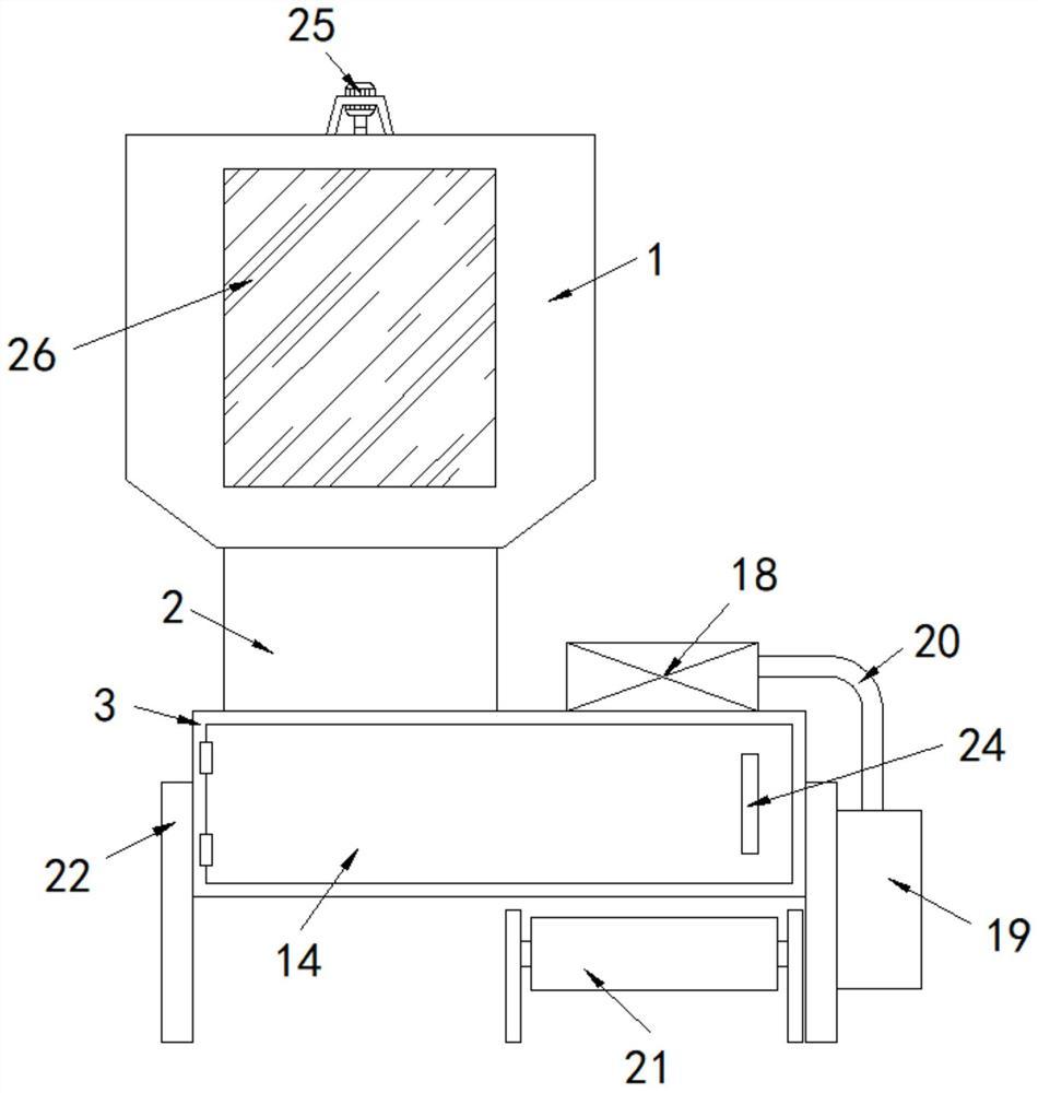
FIG. 1 is a schematic structural view of a clinker feeding device for cement production according to the present invention;
FIG. 2 is a schematic view of the internal structure of FIG. 1;
FIG. 3 is an enlarged view of the portion A of FIG. 2;
fig. 4 is an enlarged view of a portion B of fig. 2.
In the figure: the device comprises a storage bin 1, a conveying shell 2, a discharging box 3, a first rotating rod 4, a second rotating rod 5, a cross-shaped rod 6, a cross rod 7, a third rotating rod 8, a first bevel gear 9, a second bevel gear 10, a toothed ring 11, a gear 12, a conveying roller 13, a box plate 14, a fourth rotating rod 15, a belt pulley 16, a belt 17, an exhaust fan 18, a dust collecting box 19, a connecting pipe 20, a conveying belt 21, supporting feet 22, a scraper 23, a handle 24, a motor 25 and a transparent plate 26.
Detailed Description
The technical solutions in the embodiments of the present invention will be clearly and completely described below with reference to the drawings in the embodiments of the present invention, and it is obvious that the described embodiments are only a part of the embodiments of the present invention, and not all of the embodiments. All other embodiments, which can be derived by a person skilled in the art from the embodiments given herein without making any creative effort, shall fall within the protection scope of the present invention.
Referring to fig. 1-4, a clinker feeding device for cement production comprises a storage silo 1, a conveying shell 2 and a discharging box 3, wherein the conveying shell 2 is fixedly arranged at the lower end of the storage silo 1, the discharging box 3 is fixedly arranged at the lower end of the conveying shell 2, a first rotating rod 4 is rotatably arranged in the storage silo 1, second rotating rods 5 are sequentially rotatably arranged on two sides of the rod wall of the first rotating rod 4 from top to bottom, a plurality of cross-shaped rods 6 are fixedly arranged on the rod walls of the second rotating rods 5, transverse rods 7 are fixedly sleeved on the rod walls of the two ends of the first rotating rod 4, third rotating rods 8 are arranged between the two ends of the two transverse rods 7, the two ends of the two third rotating rods 8 are rotatably connected with the corresponding transverse rods 7 through first rolling bearings, first bevel gears 9 are fixedly sleeved at one ends of the outer sides of the second rotating rods 5, second bevel gears 10 are fixedly sleeved on the rod walls of the two third rotating rods 8 and at positions corresponding to the first bevel gears 9, a plurality of first bevel gears 9 are all meshed with corresponding second bevel gears 10, a toothed ring 11 is fixedly sleeved at the upper end inside the storage bin 1, gears 12 are fixedly sleeved at the upper ends of two third rotating rods 8, two gears 12 are all meshed with the toothed ring 11, a motor 25 is arranged at the top of the storage bin 1, the output end of the motor 25 is fixedly connected with the upper end of a first rotating rod 4, a conveying roller 13 is arranged inside the conveying shell 2, both ends of the conveying roller 13 are rotatably connected with the corresponding side wall of the conveying shell 2 through second rolling bearings, the upper end of the conveying roller 13 is fixedly connected with the lower end of the first rotating rod 4, the lower end of the conveying roller 13 extends into the discharging box 3, a fourth rotating rod 15 is arranged at the middle end inside the discharging box 3, both ends of the fourth rotating rod 15 are rotatably connected with the corresponding side wall of the discharging box 3 through third rolling bearings, belt pulleys 16 are fixedly sleeved on the lower end rod wall of the conveying roller 13 and the middle end rod wall of the fourth rotating rod 15, two belt pulleys 16 rotate through belt 17 and connect, and the lower extreme of fourth bull stick 15 is fixed to be cup jointed scraper blade 23 admittedly on the pole wall, and the discharge gate has been seted up to the lower surface of scraper blade 23 and the right side bottom that goes out workbin 3 that the inside bottom of play workbin 3 offsets out workbin 3, is provided with conveyer belt 21 under the discharge gate, and the exhaust port has been seted up to the right side top of play workbin 3, and the right side of going out workbin 3 is provided with dust removal mechanism.
Dust removal mechanism includes air exhauster 18, connecting pipe 20 and dust collection box 19, and air exhauster 18 is located directly over the exhaust port and is connected with the last fixed surface of ejection of compact case 3, and dust collection box 19 is fixed to be set up in the right side wall of ejection of compact case 3, and connecting pipe 20 sets up between air exhauster 18 and dust collection box 19, and the both ends of connecting pipe 20 are corresponding to air exhauster 18 and the setting of dust collection box 19 intercommunication respectively.
The front side of ejection of compact case 3 rotates through the hinge and is provided with boxboard 14, and the right side fixed surface of boxboard 14 is provided with handle 24, conveniently clears up ejection of compact case 3 is inside.
The motor 25 is fixedly connected with the storage bin 1 through the support frame, so that the motor 25 is more stable in connection with the storage bin 1.
Supporting legs 22 are fixedly arranged on both sides of the discharging box 3. The equipment is stably supported.
Logical groove has been seted up to the front side surface of storage silo 1, and the fixed transparent plate 26 that is provided with in inside that leads to the groove conveniently observes the surplus of the inside material of storage silo 1.
The cross section of the discharging box 3 is circular, so that the scraper 23 can rotate conveniently.
In conclusion, when the clinker discharging device for cement production is used, a worker switches on a power supply of the motor 25, the motor 25 drives the first rotating rod 4 to rotate, so as to drive the two third rotating rods 8 to rotate around the first rotating rod 4, so as to enable the two gears 12 to rotate in cooperation with the toothed ring 11, so as to drive the two third rotating rods 8 to rotate, so as to enable the plurality of second bevel gears 10 to drive the corresponding first bevel gears 9 to rotate, so as to drive the plurality of second rotating rods 5 to rotate, so as to enable the plurality of second rotating rods 5 to drive the plurality of cross-shaped rods 6 to rotate, so as to enable the materials to be uniformly and sufficiently crushed, meanwhile, the first rotating rod 4 drives the conveying roller 13 to rotate, so as to convey the materials to the inside of the discharging box 3 through the conveying shell 2, the conveying roller 13 drives the two belt pulleys 16 to rotate, so as to enable the fourth rotating rod 15 to drive the scraper 23 to rotate, so as to push the materials in the discharging box 3 out of the discharging port and fall onto the surface of the conveying belt 21, thereby realizing high-efficiency blanking.
It is to be noted that the term "comprises," "comprising," or any other variation thereof is intended to cover a non-exclusive inclusion, such that a process, method, article, or apparatus that comprises a list of elements does not include only those elements but may include other elements not expressly listed or inherent to such process, method, article, or apparatus. Without further limitation, an element defined by the phrase "comprising an … …" does not exclude the presence of other identical elements in a process, method, article, or apparatus that comprises the element.
Although embodiments of the present invention have been shown and described, it will be appreciated by those skilled in the art that changes, modifications, substitutions and alterations can be made in these embodiments without departing from the principles and spirit of the invention, the scope of which is defined in the appended claims and their equivalents.
- 上一篇:一种医用注射器针头装配设备
- 下一篇:一种石灰石粉制浆设备