Packaging cover plate, manufacturing method thereof and photovoltaic module
阅读说明:本技术 一种封装盖板及其制作方法、光伏组件 (Packaging cover plate, manufacturing method thereof and photovoltaic module ) 是由 吴伟 谭小春 于 2021-08-25 设计创作,主要内容包括:本发明公开一种封装盖板及其制作方法、光伏组件,涉及光伏技术领域,以使封装盖板具备柔韧性的同时,具有较好的抗冲击性能。该封装盖板应用于光伏组件,封装盖板包括耐候层和附着在耐候层上的抗冲击层;抗冲击层的材料为具有互穿网络结构的复合材料。本发明提供的封装盖板及其制作方法、光伏组件用于制造光伏组件。(The invention discloses a packaging cover plate, a manufacturing method thereof and a photovoltaic module, and relates to the technical field of photovoltaics, so that the packaging cover plate has good impact resistance while having flexibility. The packaging cover plate is applied to a photovoltaic module and comprises a weather-resistant layer and an impact-resistant layer attached to the weather-resistant layer; the material of the impact resistant layer is a composite material with an interpenetrating network structure. The packaging cover plate and the manufacturing method thereof, and the photovoltaic module are used for manufacturing the photovoltaic module.)
1. An encapsulating cover plate applied to a photovoltaic module, the encapsulating cover plate comprising a weather-resistant layer and an impact-resistant layer attached to the weather-resistant layer;
the material of the impact resistant layer is a composite material with an interpenetrating network structure.
2. The package cover plate according to claim 1, wherein the composite material comprises a flexible component and a rigid component, the flexible component and the rigid component are interwoven into an interpenetrating network structure, and the mass ratio of the flexible component to the rigid component is 1 (1-2).
3. The package cover of claim 2, wherein the flexible component comprises polyurethane or polyorganosiloxane and the rigid component comprises acrylate.
4. The package cover according to claim 3, wherein the polyurethane comprises at least one of ester polyurethane and ether polyurethane.
5. The package cover according to any one of claims 1 to 4, wherein the composite material further comprises a reinforcing material having a mass 1/3 to 2/3 times the sum of the masses of the flexible component and the rigid component; the reinforcing material is 0-dimensional, 1-dimensional, 2-dimensional or 3-dimensional; the reinforcing material is transparent material or colored material.
6. The package cover according to claim 5, wherein the reinforcing material comprises one or more of glass beads, chopped glass fibers, polymer fiber materials, 2-dimensional polymer fiber woven materials, and 3-dimensional polymer fiber woven materials.
7. The cover sheet according to any one of claims 1 to 4, wherein the weather-resistant layer is made of one or more of ETFE, ECTFE, PVDF, PVF, FEP, PET or PC; and/or the thickness of the weather-resistant layer is 20-500 mu m; and/or the light transmittance of the weather-resistant layer is more than or equal to 90 percent; and/or the impact resistant layer is transparent.
8. The cover according to any one of claims 1 to 4, wherein the cover is used as a front cover or a rear cover of a photovoltaic module.
9. A method for manufacturing the package cover plate according to any one of claims 1 to 8, comprising the following steps:
providing a first mixture, wherein the first mixture is formed by mixing a reactant of a flexible component, a flexible component crosslinking catalyst, a rigid component monomer, a rigid component crosslinking initiator and a reinforcing material;
providing a weather-resistant layer; attaching the first mixture to the surface of the weather-resistant layer to obtain a prefabricated cover plate;
processing the prefabricated cover plate at a first temperature to perform a first crosslinking reaction;
processing the prefabricated cover plate at a second temperature, and carrying out a second crosslinking reaction to obtain a packaging cover plate; wherein the first temperature is less than the second temperature.
10. The method of claim 9, wherein the surface energy of the weathering layer is greater than or equal to 38 dynes.
11. The method of claim 9, wherein providing a weathering layer comprises: carrying out surface treatment on the weather-resistant layer; the surface treatment comprises at least one of corona treatment, plasma treatment and flame treatment.
12. The method for manufacturing the package cover plate according to claim 9, wherein the reactants of the flexible component include polyether polyol, small molecule polyol and hexamethylene diisocyanate; the flexible component crosslinking catalyst is an organic tin catalyst;
the rigid component monomer comprises one or more of methyl acrylate, ethyl acrylate, n-butyl acrylate, methyl methacrylate, n-butyl methacrylate and acrylic acid modified bisphenol A epoxy resin; the rigid component crosslinking initiator is a peroxide initiator or an azo initiator, wherein the azo initiator comprises one or more of azobisisobutyronitrile, azobisisovaleronitrile and azobisisoheptonitrile.
13. The method of claim 12, wherein providing the first mixture comprises:
mixing polyether polyol and small molecular polyol at 50-70 ℃; cooling and then adding hexamethylene diisocyanate to obtain a second mixture;
mixing a rigid component monomer, a rigid component crosslinking initiator and a flexible component crosslinking catalyst to obtain a third mixture;
in the second mixture, the reinforcing material is added first, followed by the third mixture to obtain the first mixture.
14. The method for manufacturing the package cover plate according to any one of claims 9 to 13, wherein the first mixture is attached to the surface of the weather-resistant layer by: pouring, coating or printing.
15. The method for manufacturing the package cover plate according to any one of claims 9 to 13, wherein the device for attaching the first mixture to the surface of the weather-resistant layer is a coating mold;
the coating mold is formed by detachably enclosing a plurality of side walls, the shape enclosed by the coating mold is the same as that of the weather-resistant layer, and the size of the coating mold is matched with that of the weather-resistant layer.
16. The method for manufacturing the package cover plate according to any one of claims 9 to 13, wherein the first crosslinking reaction is a flexible component crosslinking reaction, the first temperature is 40 ℃ to 50 ℃, and the time for processing the prefabricated cover plate at the first temperature is 10min to 60 min; the second crosslinking reaction is a rigid component crosslinking reaction; the second temperature is 80-100 ℃; the time for processing the prefabricated cover plate at the second temperature is 10-60 min;
or the first temperature is 20-30 ℃ and the second temperature is 120-160 ℃.
17. The method for manufacturing the encapsulation cover plate according to any one of claims 9 to 13, wherein the second crosslinking reaction is completed in a photovoltaic module lamination process.
18. A photovoltaic module comprising the cover sheet according to any one of claims 1 to 8.
Technical Field
The invention relates to the technical field of photovoltaics, in particular to a packaging cover plate, a manufacturing method of the packaging cover plate and a photovoltaic module.
Background
In order to achieve a better connection between photovoltaic modules and buildings, the encapsulation cover plates of photovoltaic modules are being developed in a direction of light weight and flexibility. After the light and flexible packaging cover plate replaces glass, the weight of the photovoltaic module can be reduced, and the light and flexible packaging cover plate can have good flexibility.
However, the light flexible cover plate in the prior art often has a problem of poor impact resistance under the condition of having flexibility.
Disclosure of Invention
The invention aims to provide an encapsulation cover plate, a manufacturing method thereof and a photovoltaic module, so that the encapsulation cover plate has flexibility and better impact resistance.
In a first aspect, the present invention provides a package cover. The packaging cover plate is applied to a photovoltaic module and comprises a weather-resistant layer and an impact-resistant layer attached to the weather-resistant layer; the material of the impact resistant layer is a composite material with an interpenetrating network structure.
When the technical scheme is adopted, the packaging cover plate comprises the impact resistant layer, and the material of the impact resistant layer is a composite material with an interpenetrating network structure. Microscopically, the impact resistant layer has a three-dimensional interpenetrating network structure. The three-dimensional interpenetrating network structure is formed by mutually interpenetration of at least two crosslinking networks, has the characteristics of high elasticity and impact resistance, and ensures that the impact-resistant layer has high elasticity and impact resistance. On the one hand, the high elastic energy of the impact resistant layer can absorb impact energy and reduce the damage of mechanical impact to the packaging cover plate; and on the other hand, the impact resistance of the impact resistant layer enables the impact resistant layer to bear larger impact force, and the probability of breakage of the packaging cover plate is reduced. Therefore, the impact-resistant layer disclosed by the invention has better impact resistance. Also, the weathering layer may provide better weather resistance for the package cover. The encapsulation apron that has combined resistant time layer and shock-resistant layer has better weather-resistant ability and shock resistance, can provide better guard action for photovoltaic module's solar cell module, reduces the piece probability, ensures photovoltaic module's performance.
In addition, the interpenetrating network structure has good stability, is not sensitive to temperature and is not easy to thermally degrade, so that the heat-resistant packaging cover plate has good heat resistance, the problems of deformation and aging of the packaging cover plate can be reduced, and the service life of the packaging cover plate is prolonged.
In some implementations, the composite material includes a flexible component and a rigid component, the flexible component and the rigid component are interwoven into an interpenetrating network structure, and the mass ratio of the flexible component to the rigid component is 1 (1-2). At this time, the flexible component and the rigid component are uniformly distributed in the composite material. The flexible component can provide added elasticity to the impact resistant layer, effectively absorbing impact energy. The rigid component can enable the impact-resistant layer to have better rigidity, so that the impact-resistant layer can bear larger impact force, and the probability of breakage of the impact-resistant layer is reduced. When the flexible component and the rigid component are combined in the proportion, the impact-resistant layer can better combine the characteristics of absorbing impact energy and bearing impact, thereby achieving the aim of resisting impact.
In some implementations, the flexible component includes a polyurethane or a polyorganosiloxane. At this time, polyurethane and polyorganosiloxane, which are used as one of materials of the impact resistant layer, have better elasticity, and the manufacturing method is simple and mature, thereby being convenient for industrial application. In addition, in the process of manufacturing the anti-impact layer, the flexible components can play a role in buffering, release thermal stress and further reduce the cracking problem of the photovoltaic module. The rigid component includes an acrylate. In this case, the acrylate has good heat resistance, water resistance and ultraviolet resistance. When the material is used as one of the materials of the packaging cover plate, the mechanical impact bearing capacity of the impact resistant layer can be improved, the blocking effect of the whole impact resistant layer and the packaging cover plate on the external damp and hot environment can be improved, and the protection performance of the packaging cover plate is improved.
In some implementations, the polyurethane includes at least one of an ester polyurethane, an ether polyurethane.
In some implementations, the composite material further includes a reinforcing material. At this time, the addition of the reinforcing material can improve the mechanical property of the composite material, namely the impact-resistant layer, and reduce the probability of the fracture of the impact-resistant layer. And when the reinforcing material is combined with the interpenetrating network structure interwoven by the rigid component and the flexible component, the interpenetrating network structure can further play a role in dispersing and fixing the reinforcing material, so that the mechanical property of the whole shock-resistant layer is improved. The mass of the reinforcing material is 1/3-2/3 times of the sum of the mass of the flexible component and the rigid component. At the moment, the quality of the reinforced material is moderate, and the mechanical property of the composite material can be improved to the maximum extent while the stability of the matrix of the composite material is ensured. The reinforcing material is 0-dimensional, 1-dimensional, 2-dimensional or 3-dimensional; the reinforcing material is transparent material or colored material.
In some implementations, the reinforcing material includes one or more of glass microspheres, chopped glass fibers, polymeric fiber materials, polymeric fiber woven 2-dimensional materials, polymeric fiber woven 3-dimensional materials. When the reinforcing material is inorganic materials such as glass beads and the like, the heat resistance of the whole impact-resistant layer can be improved, and the probability of thermal degradation is reduced. In addition, when the reinforcing material is glass beads, the growth of cracks can be effectively organized, the anti-impact layer is further prevented from cracking, and the anti-impact performance of the anti-impact layer is further improved.
In some implementations, the material of the weathering layer is one or more of ETFE, ECTFE, PVDF, PVF, FEP, PET, or PC. The thickness of the weather-resistant layer is 20-500 mu m. At the moment, the weather-resistant layer is large in thickness, the impact-resistant layer and the solar cell module can be well protected, and adverse effects of the external climate environment are reduced. The light transmittance of the weather-resistant layer is greater than or equal to 90%. At this time, the weather-resistant layer has good light transmission performance and small shielding effect on sunlight, and the light absorption rate of the solar cell to be protected can be ensured. The impact resistant layer is transparent.
In some implementations, the encapsulation cover plate serves as a front encapsulation cover plate or a rear encapsulation cover plate of the photovoltaic module.
In a second aspect, the present invention provides a method for manufacturing a package cover plate described in the first aspect or any implementation manner of the first aspect. The manufacturing method comprises the following steps:
providing a first mixture, wherein the first mixture is formed by mixing a reactant of a flexible component, a flexible component crosslinking catalyst, a rigid component monomer, a rigid component crosslinking initiator and a reinforcing material;
providing a weather-resistant layer; attaching the first mixture to the surface of the weather-resistant layer to obtain a prefabricated cover plate;
processing the prefabricated cover plate at a first temperature to perform a first crosslinking reaction;
processing the prefabricated cover plate at a second temperature, and performing a second crosslinking reaction to obtain a packaging cover plate; wherein the first temperature is less than the second temperature.
The manufacturing method of the package cover plate provided by the second aspect may refer to the beneficial effects of the package cover plate described in the first aspect or any implementation manner of the first aspect.
In some implementations, the weatherable layer has a surface energy greater than or equal to 38 dynes. At this time, the surface energy of the weather-resistant layer is large. When the first mixture is contacted with the weather-resistant layer, the surface activity of the weather-resistant layer is high, molecules on the surface of the weather-resistant layer and the first mixture can form stable chemical bonds, and therefore the bonding strength of the weather-resistant layer and the first mixture, namely the weather-resistant layer and the impact-resistant layer can be realized.
In some implementations, providing a weathering layer includes: carrying out surface treatment on the weather-resistant layer; the surface treatment includes at least one of corona treatment, plasma treatment, flame treatment. The weather-resistant layer may be surface-treated to form an active functional group such as a hydroxyl group on the surface of the weather-resistant layer. These reactive functional groups can form chemical bonds with some of the materials in the first hybrid material, which can improve the adhesion of the first hybrid material to the weathering layer.
In some implementations, the reactants of the flexible component include a polyether polyol, a small molecule polyol, and hexamethylene diisocyanate; the flexible component crosslinking catalyst is an organic tin catalyst; the rigid component monomer comprises one or more of methyl acrylate, ethyl acrylate, n-butyl acrylate, methyl methacrylate, n-butyl methacrylate and acrylic acid modified bisphenol A epoxy resin; the rigid component crosslinking initiator is a peroxide initiator or an azo initiator, wherein the azo initiator comprises one or more of azobisisobutyronitrile, azobisisovaleronitrile and azobisisoheptonitrile.
In some implementations, providing the first mixture includes: mixing polyether polyol and small molecular polyol at 50-70 ℃; cooling and then adding hexamethylene diisocyanate to obtain a second mixture; mixing a rigid component monomer, a rigid component crosslinking initiator and a flexible component crosslinking catalyst to obtain a third mixture; in the second mixture, the reinforcing material is added first, followed by the third mixture to obtain the first mixture. When the first mixture is obtained by adopting the method, the second mixture is formed firstly, and then the reinforcing material is added, so that the solvent required for dissolving the reinforcing material can be omitted, and the introduction of impurities can be avoided. And finally, adding the third mixture, namely adding the flexible component crosslinking catalyst, so that crosslinking of the flexible components can be avoided under the condition of not uniformly mixing, and the composite material with the interpenetrating network structure and better performance can be prepared.
In some implementations, the first mixture is attached to the surface of the weathering layer by: pouring, coating or printing.
In some implementations, the apparatus that attaches the first mixture to the surface of the weathering layer is a coating die; the coating mould is formed by detachably enclosing a plurality of side walls, the shape enclosed by the coating mould is the same as that of the weather-resistant layer, and the size of the coating mould is matched with that of the weather-resistant layer. At this time, the coating die can be used for fixing the weather-resistant layer, the flowing range of the first mixture can be limited, the first mixture is prevented from exceeding the surface range of the weather-resistant layer, and the working efficiency can be improved.
In some implementations, the first crosslinking reaction is a flexible component crosslinking reaction, the first temperature is 40 ℃ to 50 ℃, and the time for processing the prefabricated cover plate by adopting the first temperature is 10min to 60 min; the second crosslinking reaction is a rigid component crosslinking reaction; the second temperature is 80-100 ℃; and the time for processing the prefabricated cover plate at the second temperature is 10-60 min. At this time, the crosslinking reaction of the flexible component and the crosslinking reaction of the rigid component are carried out stepwise. The network structure formed in the first crosslinking reaction can play a role in dispersing and fixing the uncrosslinked material, so that all components in the composite material can be uniformly dispersed, and the performance stability of the impact resistant layer is improved. And, the first temperature is lower than the second temperature, which can avoid the second crosslinking reaction from occurring prematurely.
In some implementations, the first temperature is 20 ℃ to 30 ℃ and the second temperature is 120 ℃ to 160 ℃.
In some implementations, the second crosslinking reaction is completed in the photovoltaic module lamination process. At the moment, the process steps can be saved, the production efficiency is improved, the energy consumption generated by heating is reduced, and the resources are saved.
In a third aspect, the present disclosure provides a photovoltaic module. The photovoltaic module comprises the packaging cover plate described in the first aspect or any implementation manner of the first aspect.
The advantages of the photovoltaic module provided by the third aspect can be obtained by referring to the advantages of the encapsulating cover plate described in the first aspect or any implementation manner of the first aspect, which is not further described herein.
Drawings
The accompanying drawings, which are included to provide a further understanding of the invention and are incorporated in and constitute a part of this specification, illustrate embodiments of the invention and together with the description serve to explain the invention and not to limit the invention. In the drawings:
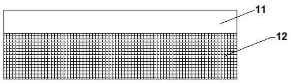
fig. 1 is a schematic structural diagram of a package cover according to an embodiment of the present invention;
fig. 2 is a schematic top view of a package cover according to an embodiment of the invention;
FIG. 3 is a schematic structural diagram of a coating die provided in an embodiment of the present invention;
fig. 4 is a schematic structural diagram of a photovoltaic module according to an embodiment of the present invention.
Reference numerals:
in fig. 1 to 4, 11-weather-resistant layer, 12-impact-resistant layer, 121-reinforcing particles, 21-front packaging cover plate, 22-first packaging adhesive film, 23-solar cell module, 24-second packaging adhesive film, 25-rear packaging cover plate, a-coating mold, and a 01-side wall.
Detailed Description
In order to facilitate clear description of technical solutions of the embodiments of the present invention, in the embodiments of the present invention, terms such as "first" and "second" are used to distinguish the same items or similar items having substantially the same functions and actions. Those skilled in the art will appreciate that the terms "first," "second," etc. do not denote any order or quantity, nor do the terms "first," "second," etc. denote any order or importance.
In the description of the present invention, it is to be understood that the terms "upper", "lower", "front", "rear", "left", "right", and the like indicate orientations or positional relationships based on those shown in the drawings, and are only for convenience of description and simplicity of description, but do not indicate or imply that the referred device or element must have a specific orientation, be constructed in a specific orientation, and be operated, and thus, should not be construed as limiting the present invention.
It is to be understood that the terms "exemplary" or "such as" are used herein to mean serving as an example, instance, or illustration. Any embodiment or design described herein as "exemplary" or "e.g.," is not necessarily to be construed as preferred or advantageous over other embodiments or designs. Rather, use of the word "exemplary" or "such as" is intended to present concepts related in a concrete fashion.
In the present invention, "at least one" means one or more, "a plurality" means two or more. "and/or" describes the association relationship of the associated objects, meaning that there may be three relationships, e.g., a and/or B, which may mean: a exists alone, A and B exist simultaneously, and B exists alone, wherein A and B can be singular or plural. The character "/" generally indicates that the former and latter associated objects are in an "or" relationship. "at least one of the following" or similar expressions refer to any combination of these items, including any combination of the singular or plural items. For example, at least one (one) of a, b, or c, may represent: a, b, c, a and b combination, a and c combination, b and c combination, or a, b and c combination, wherein a, b and c can be single or multiple.
The photovoltaic module product is combined with a building to construct an energy-saving building, and is an important means for reducing carbon emission and saving energy. There is an increasing amount of technical research on the integration of photovoltaic modules with buildings. Due to the diversity of building surface structures, the photovoltaic module products combined with the building surface structures also need to have flexibility and lower weight correspondingly. At present, a photovoltaic module mostly adopts a polymer film or a composite material as a light flexible packaging cover plate to replace glass, so as to reduce the weight of the photovoltaic module and ensure the flexibility of the whole photovoltaic module. However, such photovoltaic modules have poor mechanical strength and resistance to mechanical shock. If the whole photovoltaic module is subjected to hail weather, the cells in the whole photovoltaic module are easily broken, and the performance of the photovoltaic module is seriously attenuated.
The packaging cover plate is an important part in the whole packaging system and has a great influence on the shock resistance of the whole photovoltaic module. In the packaging cover plate in the prior art, weather-resistant powder coating is coated on fiber cloth, the weather-resistant powder is bonded with the fiber cloth through hot pressing, and then the packaging cover plate is cut to obtain the light and flexible packaging cover plate. However, the scheme is not only complex in preparation process, but also difficult in uniform coating of the powder coating; and the position of the fiber cloth is difficult to fix, and the positions of the fiber cloth in the packaging cover plate are not uniform, so that the performance of the packaging cover plate greatly fluctuates. And also has problems of poor impact resistance and poor heat resistance. The photovoltaic module manufactured by the packaging cover plate has great thermal stress, and the photovoltaic module is easy to deform seriously to cause the splitting of a battery piece.
In order to solve the above technical problem, an embodiment of the present invention provides a package cover plate. The packaging cover plate is applied to a photovoltaic module. In particular, the solar cell module 23 is used for packaging to form a photovoltaic module.
As shown in fig. 1, the above-mentioned package cover plate includes a weather-resistant layer 11 and an impact-resistant layer 12 attached on the weather-resistant layer 11; the material of the impact resistant layer 12 is a composite material with an interpenetrating network structure.
Based on the above structure, the package cover plate includes the impact resistant layer 12, and the material of the impact resistant layer 12 is a composite material with an interpenetrating network structure. Microscopically, impact resistant layer 12 has a three-dimensional interpenetrating network structure. The three-dimensional interpenetrating network structure is formed by mutually interpenetration of at least two kinds of crosslinking networks, and has the characteristics of high elasticity and impact resistance, so that the impact-resistant layer 12 has high elasticity and impact resistance. On the one hand, the high elastic energy of the impact resistant layer 12 can absorb impact energy and reduce the damage of mechanical impact to the packaging cover plate; on the other hand, the impact resistance of the impact resistant layer 12 enables the impact resistant layer to bear larger impact force, and the probability of cracking of the packaging cover plate is reduced. It can be seen that the impact resistant layer 12 of the present invention has superior impact resistance. Also, the weathering layer 11 may provide better weather resistance for the package cover. The encapsulation cover plate combined with the weather-resistant layer 11 and the impact-resistant layer 12 has good weather resistance and impact resistance, can provide a good protection effect for a solar cell module of a photovoltaic module, reduces the probability of fragments, and ensures the performance of the photovoltaic module.
In addition, the interpenetrating network structure has good stability, is not sensitive to temperature and is not easy to thermally degrade, so that the heat-resistant packaging cover plate has good heat resistance, the problems of deformation and aging of the packaging cover plate can be reduced, and the service life of the packaging cover plate is prolonged.
The packaging cover plate can be used as a front packaging cover plate of the photovoltaic module and can also be used as a rear packaging cover plate. At this moment, the encapsulation cover plate can be utilized to encapsulate and protect the front and the back of the photovoltaic module or the front and the back of the photovoltaic module according to actual needs. When the packaging cover plate provided by the embodiment of the invention is selected on one surface of the photovoltaic module, the packaging material such as glass can be selected on the other surface of the photovoltaic module. The impact resistant layer 12 made of composite material may be transparent so as to be used as a front package cover.
The material of the weather-resistant layer 11 may be one or more of ethylene-tetrafluoroethylene copolymer (ETFE), ethylene chlorotrifluoroethylene copolymer (ECTFE), polyvinylidene fluoride (PVDF), polyvinyl formal (PVF), fluoroethylene propylene copolymer (FEP), polyester resin (PET), or Polycarbonate (PC). At this time, no matter what weather-resistant material is selected, better weather resistance can be provided for the packaging cover plate.
The light transmittance of the weather-resistant layer 11 may be 90% or more. For example, the light transmittance of the weathering layer 11 may be 90%, 91%, 92%, 93%, 94%, 95%, 96%, 97%, 98%, 99%, etc. In this case, the weather-resistant layer 11 has a good light-transmitting property and a small shielding effect against sunlight, and can ensure the light absorption rate of the solar cell to be protected.
When selecting the material of the weather-resistant layer 11, it may be selected according to the use of the package cover sheet. For example, when the encapsulating cover plate is used on the front side of a photovoltaic module for single-sided power generation or a photovoltaic module for double-sided power generation, a material for the resistant layer having a high light transmittance may be selected. When the encapsulating cover plate is used on the back of a photovoltaic module with single-sided power generation, the material of the opaque weather-resistant layer 11 such as light transmission or black can be selected.
As shown in FIG. 1, the weather-resistant layer 11 may have a thickness of 20 μm to 500. mu.m. When the thickness of the weather-resistant layer 11 is in the range, the thickness of the weather-resistant layer 11 is large, the impact-resistant layer 12 and the solar cell module can be well protected, and adverse effects of the external climate environment are reduced. For example, the weatherable layer 11 may have a thickness of 20 μm, 80 μm, 100 μm, 120 μm, 200 μm, 250 μm, 300 μm, 360 μm, 400 μm, 450 μm, 500 μm, or the like.
The composite material of the impact resistant layer 12 includes a flexible component and a rigid component, and the flexible component and the rigid component are interwoven into an interpenetrating network structure. The mass ratio of the flexible component to the rigid component is 1 (1-2). Illustratively, the mass ratio of the flexible component to the rigid component may be 1:1, 1:1.2, 1:1.3, 1:1.4, 1:1.5, 1:1.6, 1:1.7, 1:1.8, 1:1.9, 1:2, and the like. At this time, the flexible component and the rigid component are uniformly distributed in the composite material. The flexible component can provide added resilience to the impact resistant layer 12, effectively absorbing impact energy. The rigid component provides impact resistant layer 12 with greater rigidity, which in turn allows impact resistant layer 12 to withstand greater impact forces and reduces the chance of impact resistant layer 12 cracking. When the flexible component and the rigid component are combined in the above ratio, the impact resistance layer 12 can be well combined with the characteristics of absorbing impact energy and bearing impact, thereby achieving the purpose of impact resistance.
The above-mentioned flexible component may include any one of polyurethane or polyorganosiloxane. In this case, polyurethane and polyorganosiloxane, which are one of the materials of the impact resistant layer 12, have not only good elasticity, but also simple and mature manufacturing method, which is convenient for industrial application. In addition, during the process of manufacturing the impact resistant layer 12, the flexible components can play a role in buffering, release thermal stress and further reduce the cracking problem of the photovoltaic module.
The polyurethane includes at least one of ester polyurethane and ether polyurethane. In practical application, the polyurethane may be ester polyurethane, ether polyurethane, or a mixture of ester polyurethane and ether polyurethane. The preferred polyurethane is an ether polyurethane.
The rigid component includes an acrylate. In this case, the acrylate has good heat resistance, water resistance and ultraviolet resistance. When the material is used as one of the materials of the packaging cover plate, the mechanical impact resistance of the impact resistance layer 12 can be improved, the blocking effect of the whole impact resistance layer 12 and the packaging cover plate on the external damp and hot environment can be improved, and the protection performance of the packaging cover plate is improved.
As shown in fig. 1 and 2, the composite material further includes a reinforcing material. At this time, the addition of the reinforcing material can improve the mechanical properties of the composite material, i.e., the impact-resistant layer 12, and reduce the possibility of cracking of the impact-resistant layer 12. Moreover, when the reinforcing material is combined with an interpenetrating network structure of interwoven rigid and flexible components, the interpenetrating network structure may further serve to disperse and fix the reinforcing material, thereby improving the mechanical properties of the entire impact-resistant layer 12.
The mass of the reinforcing material can be 1/3-2/3 times of the sum of the mass of the flexible component and the rigid component. For example, the reinforcing material may have a mass 1/3 times, 0.35 times, 0.4 times, 0.45 times, 0.48 times, 0.5 times, 0.55 times, 0.6 times, 0.63 times, 2/3 times, etc., of the sum of the masses of the flexible component and the rigid component. At the moment, the quality of the reinforced material is moderate, and the mechanical property of the composite material can be improved to the maximum extent while the stability of the matrix of the composite material is ensured.
The reinforcing material is 0-dimensional, 1-dimensional, 2-dimensional or 3-dimensional. Specifically, the reinforcing material may include one or more of glass beads, chopped glass fibers, polymer fiber materials, 2-dimensional materials woven by polymer fibers, and 3-dimensional materials woven by polymer fibers. Preferably, the reinforcing material may be 0-dimensional glass beads. When the reinforcing material is an inorganic material such as glass beads, the heat resistance of the whole impact-resistant layer 12 can be improved, and the probability of thermal degradation is reduced. In addition, when the reinforcing material is glass beads, the growth of cracks can be effectively organized, the impact-resistant layer 12 is further prevented from cracking, and the impact resistance of the impact-resistant layer 12 is further improved.
The reinforcing material can be transparent material or colored material. In this case, the transparent or colored reinforcing material may be selected according to the application of the package cover.
For example, when the encapsulating cover plate is positioned on the front surface of the photovoltaic module, the reinforcing material of the transparent material can be selected. When the encapsulation cover plate is positioned on the back of the photovoltaic module and needs color decoration, a reinforcing material made of a colored material, such as colored glass beads, colored polymer fiber materials and the like, can be selected.
The embodiment of the invention also provides a manufacturing method of the packaging cover plate. The manufacturing method of the packaging cover plate comprises the following steps:
step S100: providing a first mixture, wherein the first mixture is formed by mixing reactants of flexible components, a flexible component crosslinking catalyst, a rigid component monomer, a rigid component crosslinking initiator and a reinforcing material.
The reactants of the flexible component comprise polyether polyol, small molecular polyol and hexamethylene diisocyanate. The small molecule polyol may be pentaerythritol. The flexible component crosslinking catalyst may be an organotin-based catalyst. The organic tin catalyst can be one or more of dibutyltin dilaurate, stannous octoate, dibutyltin bis (dodecyl sulfur) and dibutyltin diacetate.
The rigid component monomer can comprise one or more of methyl acrylate, ethyl acrylate, n-butyl acrylate, methyl methacrylate, n-butyl methacrylate and acrylic acid modified bisphenol A epoxy resin. The rigid component crosslinking initiator can be a peroxide initiator or an azo initiator. The azo initiator comprises one or more of azobisisobutyronitrile, azobisisovaleronitrile and azobisisoheptonitrile. These materials can be used to make interpenetrating network structure of polyurethane and acrylate. With these materials, it is possible to ensure that the crosslinking reaction proceeds stably and rapidly.
There are various ways of obtaining the first mixture, as long as uniform mixing is ensured. Illustratively, the reactants of the flexible components, the flexible component crosslinking catalyst, the rigid component monomer, the rigid component crosslinking initiator, the reinforcing material, and the first mixture may be simultaneously added to a mixing vessel and rapidly attached to the weathering layer 11.
Illustratively, providing the first mixture includes:
step S101: mixing polyether polyol and small molecular polyol at 50-70 ℃; after cooling, hexamethylene diisocyanate was added to obtain a second mixture. In the process, the polyether polyol and the small molecular polyol can be quickly and uniformly mixed at the temperature of 50-70 ℃. After cooling, hexamethylene diisocyanate is added, and at a lower temperature, the reactants of the flexible components can be prevented from reacting too fast without mixing uniformly.
Step S102: mixing a rigid component monomer, a rigid component crosslinking initiator, and a flexible component crosslinking catalyst to obtain a third mixture. It should be understood that the order of step S101 and step S102 may be reversed.
Step S103: in the second mixture, the reinforcing material is added first, followed by the third mixture to obtain the first mixture. When the first mixture is obtained by adopting the method, the second mixture is formed firstly, and then the reinforcing material is added, so that the solvent required for dissolving the reinforcing material can be omitted, and the introduction of impurities can be avoided. And finally, adding the third mixture, namely adding the flexible component crosslinking catalyst, so that crosslinking of the flexible components can be avoided under the condition of not uniformly mixing, and the composite material with the interpenetrating network structure and better performance can be prepared.
Step S200: a weathering layer 11 is provided. The weatherable layer 11 can have a surface energy greater than or equal to 38 dynes. For example, the surface energy of the weathering layer 11 may be 38 dynes, 40 dynes, 42 dynes, 45 dynes, 50 dynes, 60 dynes, 70 dynes, and the like. At this time, the surface energy of the weathering layer 11 is large. When the first mixture is in contact with the weathering layer 11, the surface activity of the weathering layer 11 is large, and molecules on the surface of the weathering layer 11 can form stable chemical bonds with the first mixture, thereby enabling the bonding strength of the weathering layer 11 and the first mixture, i.e., the weathering layer 11 and the impact resistant layer 12.
Providing a weathering layer 11 may also include: carrying out surface treatment on the weather-resistant layer 11; the surface treatment includes at least one of corona treatment, plasma treatment, flame treatment. It is to be understood that the surface energy of the weathering layer 11 may be greater than or equal to 38 dynes after the surface treatment of the weathering layer 11. The weather-resistant layer 11 may be surface-treated to form an active functional group such as a hydroxyl group on the surface of the weather-resistant layer 11. These reactive functional groups are capable of forming chemical bonds with some of the substances in the first mixture material, which in turn may improve the adhesion of the first mixture to the weathering layer 11.
In practical applications, step S100 may be executed first, and then step S200 may be executed; step S200 may be executed first, and then step S100 may be executed; step S100 and step S200 may also be performed simultaneously.
Step S300: the first mixture is attached to the surface of the weathering layer 11 to obtain a prefabricated cover plate. The first mixture is attached to the surface of the weathering layer 11 in the following manner: pouring, coating or printing. Due to the good fluidity of the first mixture, the first mixture can be quickly and uniformly attached to the surface of the weathering layer 11 by pouring, coating, printing, etc. Also, when the coating and printing method is used, a multi-layered first mixture, that is, a multi-layered composite material, may be formed on the surface of the weathering layer 11.
The apparatus for attaching the first mixture to the surface of the weathering layer 11 is a coating die a. As shown in fig. 3, the coating mold a is formed by detachably enclosing a plurality of side walls a01, the shape enclosed by the coating mold a is the same as the shape of the weather-resistant layer 11, and the size of the coating mold a is matched with the size of the weather-resistant layer 11. At this time, not only the weathering layer 11 can be fixed by the coating die a, but also the flow range of the first mixture can be restricted, the first mixture is prevented from exceeding the surface range of the weathering layer 11, and the working efficiency can be improved.
For example, as shown in fig. 3, when the weathering layer 11 has a rectangular shape, the coating mold a may be detachably enclosed by four side walls a01 to form a rectangular frame. And, the rectangular frame is slightly larger than the size of the weathering layer 11 so that the weathering layer 11 is put into the rectangular frame.
In use, the weather-resistant layer 11 is placed in a coating mold a in a flat manner, and then the first mixture is poured onto the surface of the weather-resistant layer 11 so that the first mixture uniformly covers the surface of the weather-resistant layer 11. After the first mixture is crosslinked to form the impact resistant layer 12, the coating die a is removed.
Step S400: the preformed cover plate is processed at a first temperature to perform a first crosslinking reaction.
Step S500: processing the prefabricated cover plate at a second temperature, and performing a second crosslinking reaction to obtain a packaging cover plate; wherein the first temperature is less than the second temperature. In practice, the temperature is first set to a first temperature, with which the first mixture is subjected to a first crosslinking reaction. The temperature is then raised to a second temperature, and the second temperature is used to further complete a second crosslinking reaction of the first mixture to form impact resistant layer 12.
Specifically, the first crosslinking reaction and the second crosslinking reaction may be performed in various ways. For example: the first crosslinking reaction is a flexible component crosslinking reaction, the first temperature is 40-50 ℃, and the time for processing the prefabricated cover plate at the first temperature is 10-60 min. The second crosslinking reaction is a rigid component crosslinking reaction, and the second temperature is 80-100 ℃; and the time for processing the prefabricated cover plate at the second temperature is 10-60 min. At this time, the crosslinking reaction of the flexible component and the crosslinking reaction of the rigid component are carried out stepwise. The network structure formed in the first crosslinking reaction can disperse and fix the uncrosslinked material, so that the components in the composite material can be uniformly dispersed, and the performance stability of the impact-resistant layer 12 is improved. And, the first temperature is lower than the second temperature, which can avoid the second crosslinking reaction from occurring prematurely.
Illustratively, the first temperature may be 40 ℃, 42 ℃, 43 ℃, 44 ℃, 45 ℃, 46 ℃, 47 ℃, 48 ℃, 49 ℃, 50 ℃ or the like. The second temperature can be 80 deg.C, 82 deg.C, 85 deg.C, 88 deg.C, 90 deg.C, 91 deg.C, 93 deg.C, 96 deg.C, 97 deg.C, 99 deg.C, 100 deg.C, etc. The time for processing the prefabricated cover plate at the first temperature and the time for processing the prefabricated cover plate at the second temperature can be 10min, 15min, 20min, 30min, 40min, 50min, 60min and the like.
As another example, the first crosslinking reaction includes a flexible component crosslinking reaction and a rigid crosslinking reaction, but curing is incomplete, and the second crosslinking reaction completely cures the first mixture at an elevated temperature to form the impact resistant layer 12. In this manner, the first temperature may be in the range of 20 ℃ to 30 ℃. For example, the first temperature may be 20 ℃, 22 ℃, 25 ℃, 27 ℃, 29 ℃, 30 ℃ or the like. The second temperature may be 120 ℃ to 160 ℃. For example, the second temperature may be 120 ℃, 130 ℃, 135 ℃, 140 ℃, 150 ℃, 155 ℃, 160 ℃ or the like. At this time, the first mixture is first subjected to a first crosslinking reaction in a room temperature environment, and most of the crosslinking curing of the impact resistance layer 12 is also completed. The first mixture is then fully cured using a higher temperature to form impact resistant layer 12. In this manner, the second crosslinking reaction can be completed in the photovoltaic module lamination process. At the moment, the process steps can be saved, the production efficiency is improved, the energy consumption generated by heating is reduced, and the resources are saved.
When the packaging cover plate is manufactured by the method, the interpenetrating network structure of the composite material is manufactured through the first crosslinking reaction and the second crosslinking reaction, so that the mutual influence between the two network structures can be reduced, the phase separation is reduced, and the performance of the impact-resistant layer 12 is improved. Moreover, the weather-resistant layer 11 is made of materials such as PET, and compared with fiber cloth, the position fluctuation in the packaging material is small, so that the stability of the packaging cover plate is good. In addition, the manufacturing method of the packaging cover plate only needs to attach the first mixture on the surface of the weather-resistant layer 11, carries out two times of different temperature treatment and saves lessons, and has simple process and low manufacturing difficulty, thereby reducing the production cost and improving the manufacturing efficiency.
The embodiment of the invention also provides a photovoltaic module. The photovoltaic module comprises the packaging cover plate. Illustratively, as shown in fig. 4, the photovoltaic module specifically includes a front encapsulation cover plate 21, a first encapsulation adhesive film 22, a solar cell module 23, a second encapsulation adhesive film 24, and a rear encapsulation cover plate 25.
The front package cover 21 is the package cover provided in the embodiment of the present invention. The first adhesive film 22 and the second adhesive film 24 are made of any one of EVA, POE, PVB, PDMS, or ionomer. The light transmittance of the first packaging adhesive film 22 and the second packaging adhesive film 24 is greater than or equal to 90%. The gram weights of the first packaging adhesive film 22 and the second packaging adhesive film 24 are both more than or equal to 360g/m2. The photovoltaic cell included in the solar cell module 23 may be a double-sided power generation cell. Specifically, the battery piece can be a cut 1/N battery piece, and N is more than or equal to 2. The battery pieces are connected into a battery string through the interconnecting strips, the battery string at least comprises 2 battery pieces, and the distance between the battery pieces can be 1 mm-5 mm. The battery strings are connected with each other through bus bars, the solar battery modules 23 are formed according to certain circuit requirements, one solar battery module 23 at least comprises 2 battery strings, and the distance between the battery strings is more than or equal to 0.5 mm. The back cover 25 may be a conventional solar back sheet for photovoltaic module, such as any one of TPT, TPO, TPC, KPE, KPC, KPO. Of course, the rear package cover 25 may also be the package cover provided in the embodiments of the present invention.
The front packaging cover plate 21, the first packaging adhesive film 22, the solar cell module 23, the second packaging adhesive film 24 and the rear packaging cover plate 25 are sequentially stacked, and then laminated by a press to obtain a photovoltaic module product.
While the invention has been described in connection with various embodiments, other variations to the disclosed embodiments can be understood and effected by those skilled in the art in practicing the claimed invention, from a review of the drawings, the disclosure, and the appended claims. In the claims, the word "comprising" does not exclude other elements or steps, and the word "a" or "an" does not exclude a plurality. The mere fact that certain measures are recited in mutually different dependent claims does not indicate that a combination of these measures cannot be used to advantage.
While the invention has been described in conjunction with specific features and embodiments thereof, it will be evident that various modifications and combinations can be made thereto without departing from the spirit and scope of the invention. Accordingly, the specification and figures are merely exemplary of the invention as defined in the appended claims and are intended to cover any and all modifications, variations, combinations, or equivalents within the scope of the invention. It will be apparent to those skilled in the art that various changes and modifications may be made in the present invention without departing from the spirit and scope of the invention. Thus, if such modifications and variations of the present invention fall within the scope of the claims of the present invention and their equivalents, the present invention is also intended to include such modifications and variations.
- 上一篇:一种医用注射器针头装配设备
- 下一篇:一种背接触太阳能电池、组件和系统